10-3
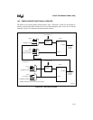
EVENT PROCESSOR ARRAY (EPA)
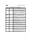
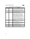
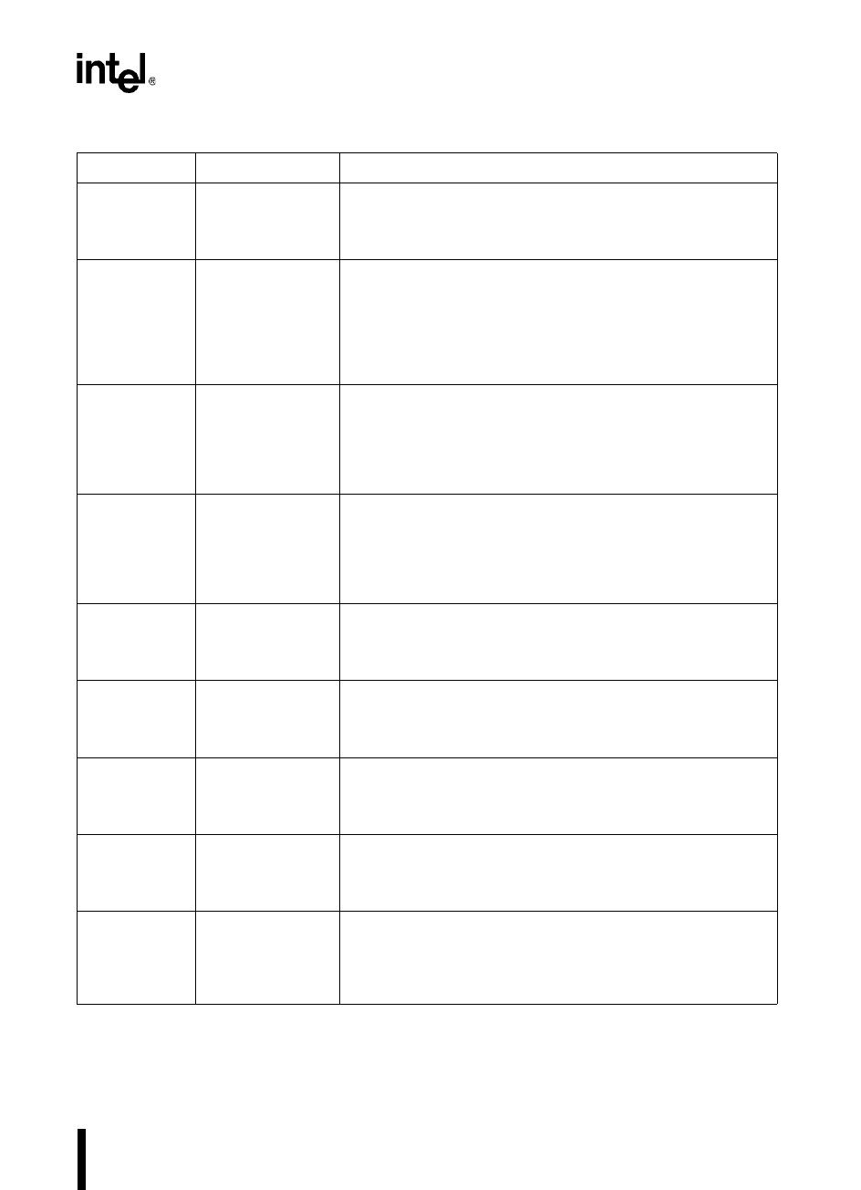
Table 10-2. EPA Control and Status Registers
Mnemonic Address Description
EPA_MASK 1F9CH EPA Mask
Four bits (OVR0, OVR1, OVR2, and OVR3) in this 8-bit register
enable and disable (mask) the individual capture overrun interrupt
sources associated with capture/compare channels EPA3:0.
EPA_PEND 1F9EH EPA Pending
Four bits (OVR0, OVR1, OVR2, and OVR3) in this 8-bit register
indicate an overrun status for the associated capture/compare
channels, EPA3:0. OVR0 and OVR1 are multiplexed to share one
interrupt pending bit (OVR0_1) in INT_PEND1; OVR2 and OVR3
are multiplexed to share another interrupt pending bit (OVR2_3)
in INT_PEND1.
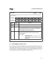
EPA0_CON
EPA1_CON
EPA2_CON
EPA3_CON
1F80H
1F84H
1F88H
1F8CH
EPA
x
Capture/Compare
Control
These registers control the functions of the capture/compare
channels. EPA1_CON and EPA3_CON require an extra byte
because they contain an additional bit for PWM remap mode.
These two registers must be addressed as words; the others can
be addressed as bytes.
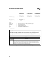
EPA0_TIME
EPA1_TIME
EPA2_TIME
EPA3_TIME
1F82H
1F86H
1F8AH
1F8EH
EPA
x
Capture/Compare Time
In capture mode, these registers contain the captured timer value.
In compare mode, these registers contain the time at which an
event is to occur. In capture mode, these registers are buffered to
allow two captures before an overrun occurs. However, they are
not buffered in compare mode.
INT_MASK 0008H Interrupt Mask
Three bits in this 8-bit register (OVRTM1, OVRTM2, and EPA0)
enable and disable (mask) the three interrupts associated with the
corresponding bits in INT_PEND register.
INT_MASK1 0013H Interrupt Mask 1
Five bits in this 8-bit register (EPA1, EPA2, EPA3, OVR0_1, and
OVR2_3) enable and disable (mask) the five interrupts associated
with the corresponding bits in INT_PEND1 register.
INT_PEND 0009H Interrupt Pending
Any set bit in this 8-bit register indicates a pending interrupt. The
three bits associated with EPA interrupts are OVRTM1, OVRTM2,
and EPA0.
INT_PEND1 0012H Interrupt Pending 1
Any set bit in this 8-bit register indicates a pending interrupt. The
five bits associated with EPA interrupts are EPA1, EPA2, EPA3,
OVR0_1, and OVR2_3.
P1_DIR 1FD2H Port 1 Direction
Each bit of P1_DIR controls the direction of the corresponding
pin. Clearing a bit configures a pin as a complementary output;
setting a bit configures a pin as an input or open-drain output.
(Open-drain outputs require external pull-ups.)


