B-11
SIGNAL DESCRIPTIONS
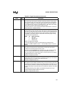
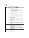
RPD I Return from Powerdown
Timing pin for the return-from-powerdown circuit.
If your application uses powerdown mode, connect a capacitor
†
between RPD
and V
SS
if either of the following conditions are true.
• the internal oscillator is the clock source
• the phase-locked loop (PLL) circuitry (80C196NU only) is enabled (see
PLLEN2:1 signal description)
The capacitor causes a delay that enables the oscillator and PLL circuitry to
stabilize before the internal CPU and peripheral clocks are enabled.
The capacitor is not required if your application uses powerdown mode and if
both of the following conditions are true.
• an external clock input is the clock source
• the phase-locked loop circuitry (80C196NU only) is disabled
If your application does not use powerdown mode, leave this pin unconnected.
†
Calculate the value of the capacitor using the formula found on page 12-11.
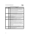
RXD I/O Receive Serial Data
In modes 1, 2, and 3, RXD receives serial port input data. In mode 0, it
functions as either an input or an open-drain output for data.
RXD is multiplexed with P2.1.
T1CLK I Timer 1 External Clock
External clock for timer 1. Timer 1 increments (or decrements) on both rising
and falling edges of T1CLK. Also used in conjunction with T1DIR for quadrature
counting mode.
and
External clock for the serial I/O baud-rate generator input (program selectable).
T1CLK is multiplexed with P1.4.
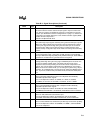
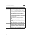
T2CLK I Timer 2 External Clock
External clock for timer 2. Timer 2 increments (or decrements) on both rising
and falling edges of T2CLK. Also used in conjunction with T2DIR for quadrature
counting mode.
T2CLK is multiplexed with P1.6.
T1DIR I Timer 1 External Direction
External direction (up/down) for timer 1. Timer 1 increments when T1DIR is high
and decrements when it is low. Also used in conjunction with T1CLK for
quadrature counting mode.
T1DIR is multiplexed with P1.5.
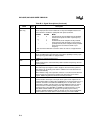
T2DIR I Timer 2 External Direction
External direction (up/down) for timer 2. Timer 2 increments when T2DIR is high
and decrements when it is low. Also used in conjunction with T2CLK for
quadrature counting mode.
T2DIR is multiplexed with P1.7.
TXD O Transmit Serial Data
In serial I/O modes 1, 2, and 3, TXD transmits serial port output data. In mode
0, it is the serial clock output.
TXD is multiplexed with P2.0.
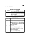
Table B-3. Signal Descriptions (Continued)
Name Type Description


