8XC196NP, 80C196NU USER’S MANUAL
2-4
2.3.3 Register Arithmetic-logic Unit (RALU)
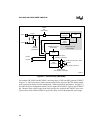
The RALU contains the microcode engine, the 16-bit arithmetic logic unit (ALU), the master pro-
gram counter (PC), the processor status word (PSW), and several registers. The registers in the
RALU are the instruction register, a constants register, a bit-select register, a loop counter, and
three temporary registers (the upper-word, lower-word, and second-operand registers).
The 24-bit master program counter (PC) provides a linear, nonsegmented 16-Mbyte memory
space. Only 20 of the address lines are implemented with external pins, so you can physically ad-
dress only 1 Mbyte. (For compatibility with earlier devices, the PC can be configured as 16 bits
wide.) The master PC contains the address of the next instruction and has a built-in incrementer
that automatically loads the next sequential address. However, if a jump, interrupt, call, or return
changes the address sequence, the ALU loads the appropriate address into the master PC.
The PSW contains one bit (PSW.1) that globally enables or disables servicing of all maskable in-
terrupts, one bit (PSW.2) that enables or disables the peripheral transaction server (PTS), and six
Boolean flags that reflect the state of your program. Appendix A, “Instruction Set Reference,”
provides a detailed description of the PSW.
All registers, except the 3-bit bit-select register and the 6-bit loop counter, are either 16 or 17 bits
(16 bits plus a sign extension). Some of these registers can reduce the ALU’s workload by per-
forming simple operations.
The RALU uses the upper- and lower-word registers together for the 32-bit instructions and as
temporary registers for many instructions. These registers have their own shift logic and are used
for operations that require logical shifts, including normalize, multiply, and divide operations.
The six-bit loop counter counts repetitive shifts. The second-operand register stores the second
operand for two-operand instructions, including the multiplier during multiply operations and the
divisor during divide operations. During subtraction operations, the output of this register is com-
plemented before it is moved into the ALU.
The RALU speeds up calculations by storing constants (e.g., 0, 1, and 2) in the constants register
so that they are readily available when complementing, incrementing, or decrementing bytes or
words. In addition, the constants register generates single-bit masks, based on the bit-select reg-
ister, for bit-test instructions.
2.3.3.1 Code Execution
The RALU performs most calculations for the device, but it does not use an accumulator. Instead
it operates directly on the lower register file, which essentially provides 256 accumulators. Be-
cause data does not flow through a single accumulator, the device’s code executes faster and more
efficiently.


