


Configuration and Use Manual 91
Measurement Performance
Measurement Performance DefaultsTroubleshootingCompensation
10.3 Performing meter verification
10.3.1 Preparing for the meter verification test
Process fluid and process conditions
The meter verification test can be performed on any process fluid. It is not necessary to match factory
conditions.
During the test, process conditions must be stable. To maximize stability:
• Maintain a constant temperature and pressure.
• Avoid changes to fluid composition (e.g., two-phase flow, settling, etc.).
• Maintain a constant flow. For higher test certainty, reduce or stop flow.
If stability varies outside test limits, the test will be aborted. Verify the stability of the process and
repeat the test.
Transmitter configuration
Meter verification is not affected by any parameters configured for flow, density, or temperature. It is
not necessary to change the transmitter configuration.
Control loops and process measurement
If the transmitter outputs will be set to Last Measured Value or Fault during the test, the outputs will
be fixed for two minutes (Smart Meter Verification) or three minutes (original version). Disable all
control loops for the duration of the test, and ensure that any data reported during this period is
handled appropriately.
Specification uncertainty limit
The specification uncertainty limit defines the acceptable degree of variation from factory results,
expressed as a percentage. Variation inside the limit is reported as Pass. Variation outside the limit is
reported as Fail or Caution.
• In Smart Meter Verification, the specification uncertainty limit is set at the factory and cannot
be configured.
• In the original version of meter verification, the specification uncertainty limit is configurable.
However, Micro Motion suggests using the default value. Contact Micro Motion Customer
Service before changing the specification uncertainty limit.
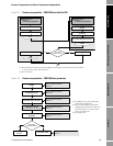
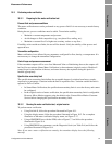
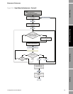
10.3.2 Running the meter verification test, original version
To perform meter verification:
• Using ProLink II, follow the procedure illustrated in Figure 10-1.
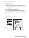
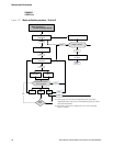
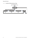
• Using the display menu, follow the procedure illustrated in Figure 10-2. For a complete
illustration of the meter verification display menu, see Figure C-17.
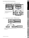
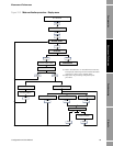
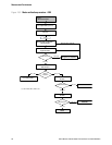
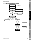
• Using a PROFIBUS host with the EDD, refer to Figure C-7 and follow the procedure
illustrated in Figure 10-4.
• Using PROFIBUS bus parameters, use the Diagnostic block (see Table D-4) and follow the
procedure illustrated in Figure 10-4.
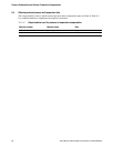
Note: If you start a meter verification test remotely, the transmitter display shows the following
message: