


Configuration and Use Manual 25
Required Configuration Optional ConfigurationUsing the TransmitterUsing a PROFIBUS Host
Chapter 6
Required Transmitter Configuration
6.1 Overview
This chapter describes the configuration procedures that are usually required when a transmitter is
installed for the first time.
The following procedures are discussed:
• Characterizing the flowmeter – see Section 6.2
• Configuring measurement units – see Section 6.3
This chapter provides basic flowcharts for each procedure. For more detailed flowcharts, see the
flowcharts for your communication tool, provided in the appendices to this manual.
For optional transmitter configuration parameters and procedures, see Chapter 8.
Note: All procedures provided in this chapter assume that you have established communication with
the Model 2400S DP transmitter and that you are complying with all applicable safety requirements.
Note: If you are using Pocket ProLink, the interface is similar to the ProLink II interface described in
this chapter.
6.2 Characterizing the flowmeter
Characterizing the flowmeter adjusts the transmitter to compensate for the unique traits of the sensor
it is paired with. The characterization parameters, or calibration parameters, describe the sensor’s
sensitivity to flow, density, and temperature.
6.2.1 When to characterize
If the transmitter and sensor were ordered together, then the flowmeter has already been
characterized. You need to characterize the flowmeter only if the transmitter and sensor are being
paired together for the first time.
6.2.2 Characterization parameters
The characterization parameters that must be configured depend on your flowmeter’s sensor type:
“T-Series” or “Other” (also referred to as “Straight Tube” and “Curved Tube,” respectively), as listed
in Table 6-1. The “Other” category includes all Micro Motion sensors except T-Series.
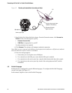
The characterization parameters are provided on the sensor tag. See Figure 6-1 for illustrations of
sensor tags.