


Configuration and Use Manual 9
Startup Using ProLink IITransmitter User InterfaceBefore You Begin
Chapter 3
Using the Transmitter User Interface
3.1 Overview
This chapter describes the user interface of the Model 2400S DP transmitter. The following topics are
discussed:
• Transmitters without or with display – see Section 3.2
• Removing and replacing the transmitter housing cover – see Section 3.3
•Using the
Scroll and Select optical switches – see Section 3.4
• Using the display – see Section 3.5
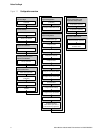
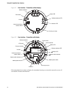
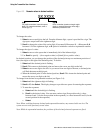
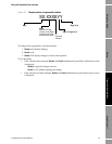
3.2 User interface without or with display
The user interface of the Model 2400S DP transmitter depends on whether it was ordered with or
without a display:
• If ordered without a display, there is no LCD panel on the user interface. The user interface
provides the following features and functions:
- Three address switches, used to set the PROFIBUS node address
- An internal termination resistor switch
- Three LEDs: a status LED, a network LED, and a software address LED
- Service port clips
- Zero button
For all other functions, either ProLink II or a customer-supplied PROFIBUS host is required.
• If ordered with a display, no zero button is provided (you must zero the transmitter with the
display menu, ProLink II, or a PROFIBUS host), and the following features are added:
- An LCD panel, which displays process variable data and also provides access to the
off-line menu for basic configuration and management. Optical switches are provided for
LCD control.
- An IrDA port which provides wireless access to the service port
Note: The off-line menu does not provide access to all transmitter functionality; for access to all
transmitter functionality, either ProLink II, the EDD, or PROFIBUS bus parameters must be used.
Figures 3-1 and 3-2 show the user interface of the Model 2400S DP transmitter without and with a
display. In both illustrations, the transmitter housing cover has been removed.