


62 Micro Motion
®
Model 2400S Transmitters for PROFIBUS-DP
Optional Configuration
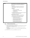
To configure slug flow parameters:
• Using ProLink II, see Figure C-2.
• Using a PROFIBUS host with the EDD, see Figure C-8.
• Using PROFIBUS bus parameters, use the Diagnostic block (see Table D-4), Indices 1, 2,
and 3.
Note: This functionality cannot be configured via the display menus.
Note: The slug flow limits must be entered in g/cm
3
, even if another unit has been configured for
density. Slug flow duration is entered in seconds. Raising the low slug flow limit or lowering the high
slug flow limit will increase the possibility of slug flow conditions. Conversely, lowering the low slug
flow limit or raising the high slug flow limit will decrease the possibility of slug flow conditions. If
slug flow duration is set to 0, the mass flow rate will be forced to 0 as soon as slug flow is detected.
8.8 Configuring status alarm severity
The 2400S DP transmitter can report faults in the following ways:
• Setting the “alarm active” status bit
• Writing an “alarm active” record to alarm history
• Implementing the digital communications fault action (see Section 8.10.7)
Status alarm severity determines which methods the transmitter will use when a specific alarm
condition occurs. See Table 8-8. (For a more extensive discussion of status alarm processing and
handling, see Section 7.7.)
Some alarms can be reclassified. For example:
• The default severity level for Alarm A020 (calibration factors unentered) is
Fault, but you can
reconfigure it to either
Informational or Ignore.
• The default severity level for Alarm A102 (drive over-range) is
Informational, but you can
reconfigure it to either
Ignore or Fault.
For a list of all status alarms and default severity levels, see Table 8-8. (For more information on
status alarms, including possible causes and troubleshooting suggestions, see Table 11-2.)
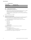
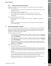
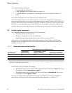
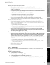
Table 8-7 Alarm severity levels and fault reporting
Severity level
Transmitter action if condition occurs
“Alarm active”
status bit set?
“Alarm active” record
written to history? Fault action activated?
(1)
(1) For some alarms, the digital communications fault action will not begin until the fault timeout has expired. To configure fault timeout,
see Section 8.8. Other fault reporting methods occur as soon as the fault condition is recognized. Table 8-8 includes information on
which alarms are affected by the fault timeout.
Fault Yes Yes Yes
Informational Yes Yes No
Ignore Yes No No