


Configuration and Use Manual 165
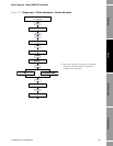
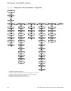
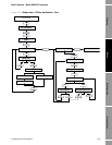
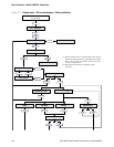
Menus Display CodesBus ParametersDiagrams
Appendix D
PROFIBUS Bus Parameters
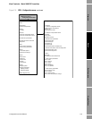
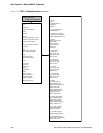
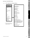
D.1 Overview
This appendix documents the bus parameters that are included in the PROFIBUS blocks. The
following blocks are documented:
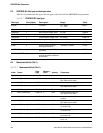
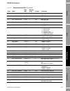
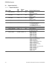
• Measurement block (Slot 1) – see Table D-2
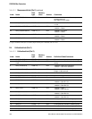
• Calibration block (Slot 2) – see Table D-3
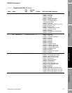
• Diagnostic block (Slot 3) – see Table D-4
• Device information block (Slot 4) – see Table D-5
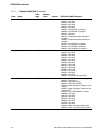
• Local display block (Slot 5) – see Table D-6
• API block (Slot 6) – see Table D-7
• Enhanced density block (Slot 7) – see Table D-8
• I&M functions block (Slot 0) – see Table D-9
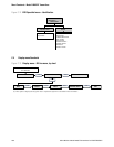
The following codes are documented:
• Totalizer and inventory measurement unit codes – see Tables D-10 through D-12
• Process variable codes – see Table D-13
• Alarm index codes – see Table D-14
Note: For measurement unit codes used for process variables, see Section 6.3.
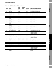
For each block, all parameters contained in the block are listed. For each parameter, the following are
documented:
• Index – the index of the parameter within the block
• Name – the name used for this parameter in the code
• Data type – the data type of the parameter (see Section D.2)
• Memory class – the class of memory required by the parameter, and the update rate (in Hz) if
applicable:
- D = dynamic store (cyclic data – parameter updated periodically)
- S = static store (acyclic data – parameter changed on a deliberate write)
- N = nonvolatile parameter (retained across power cycles)
• Access
-R = Read-only
- R/W = Read/write