


Configuration and Use Manual 11
Using the Transmitter User Interface
Startup Using ProLink IITransmitter User InterfaceBefore You Begin
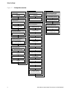
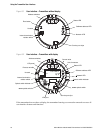
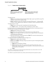
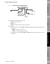
If the transmitter has a display, the transmitter housing cover has a lens. All of the features shown in
Figure 3-2 are visible through the lens, and the following functions may be performed through the
lens (i.e., with the transmitter housing cover in place):
• Viewing the LEDs
• Viewing the LCD panel
•Using the
Select and Scroll optical switches
• Making a service port connection via the IrDA port
All other functions require removal of the transmitter housing cover.
For information on:
• Using the address switches, see Section 8.10.1.
• Using the LEDs, see Section 7.5.
• Making a service port connection, see Section 4.4.
• Using the zero button, see Section 10.5.
Note: The termination resistor switch is used to enable or disable the internal terminator. The internal
terminator can be used instead of an external terminator if termination is required at the transmitter.
3.3 Removing and replacing the transmitter housing cover
For some procedures, you must remove the transmitter housing cover. To remove the transmitter
housing cover:
1. If the transmitter is in a Division 2 or Zone 2 area, remove power from the unit.
2. Loosen the four captive screws.
3. Lift the transmitter housing cover away from the transmitter.
When replacing the transmitter housing cover, be sure to adjust the cover and tighten the screws so
that no moisture can enter the transmitter housing.
3.4 Using the optical switches
Note: This section applies only to transmitters with a display.
The
Scroll and Select optical switches are used to navigate the display menus. To activate an optical
switch, touch the lens in front of the optical switch or move your finger over the optical switch close
to the lens. There are two optical switch indicators: one for each switch. When an optical switch is
activated, the associated optical switch indicator is a solid red.
WARNING
Removing the transmitter housing cover in a Division 2 or Zone 2 area while
the transmitter is powered up can cause an explosion.
To avoid the risk of an explosion, remove power from the transmitter before
removing the transmitter housing cover.