


138 Micro Motion
®
Model 2400S Transmitters for PROFIBUS-DP
Troubleshooting
11.21 Checking sensor circuitry
Problems with sensor circuitry can cause several alarms, including sensor failure and a variety of
out-of-range conditions. Testing involves:
• Inspecting the cable that connects the transmitter to the sensor
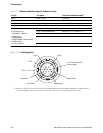
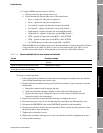
• Measuring the resistances of the sensor's pin pairs
• Ensuring that the circuits are not shorted to each other or to the sensor case
Note: To check the sensor circuitry, you must remove the transmitter from the sensor. Before
performing this test, ensure that all other applicable diagnostics have been performed. Diagnostic
capabilities of the Model 2400S transmitter have been greatly enhanced, and may provide more useful
information than these tests.
1. Follow appropriate procedures to ensure that the process of checking the sensor circuitry does
not interfere with existing measurement and control loops.
2. Power down the transmitter.
3. If the transmitter is in a hazardous environment, wait five minutes.
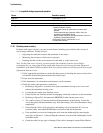
4. Check the sensor cable and sensor connection:
a. Referring to Figure B-1, loosen the four captive transmitter housing cover screws and
remove the transmitter housing cover.
b. Loosen the two captive user interface screws.
c. Gently lift the user interface module, disengaging it from the connector on the transmitter.
d. Referring to Figure B-2, disconnect the PROFIBUS cable and the power wires.
e. Two captive screws (2.5 mm hex head) hold the transmitter in the housing. Loosen the
screws and gently lift the transmitter away from the housing. Allow the transmitter to hang
temporarily.
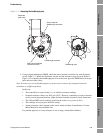
f. Ensure that the cable is fully plugged in and making a good connection. If it was not,
reseat the cable, reassemble the transmitter and sensor, and check operation.
g. If the problem is not resolved, unplug the cable from the feedthrough by removing the
snap clip (see Figure 11-1), then pulling the connector away from the feedthrough. Set the
transmitter aside.
h. Check the cable for any signs of damage. If the cable is damaged, contact Micro Motion.
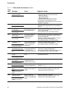
Table 11-6 Low pickoff voltage causes and remedies
Cause Possible remedy
Slug flow • See Section 11.14.
No tube vibration in sensor • Check for plugging.
Moisture in the sensor electronics • Eliminate the moisture in the sensor electronics.
Damaged sensor • Ensure sensor is free to vibrate (no mechanical binding).
Possible problems include:
- Pipe stress. Check for pipe stress and eliminate if
present.
- Lateral tube shift due to hammer effect. If this is a
possibility, contact Micro Motion.
- Warped tubes caused by overpressurization. If this is a
possibility, contact Micro Motion.
• Test sensor circuitry. See Section 11.21.
• Contact Micro Motion.