


Configuration and Use Manual 51
Required Configuration Optional ConfigurationUsing the TransmitterUsing a PROFIBUS Host
Chapter 8
Optional Configuration
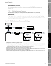
8.1 Overview
This chapter describes transmitter configuration parameters that may or may not be used, depending
on your application requirements. For required transmitter configuration, see Chapter 6.
Table 8-1 lists the parameters that are discussed in this chapter. Default values and ranges for the most
commonly used parameters are provided in Appendix A.
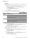
Note: All procedures provided in this chapter assume that you have established communication with
the Model 2400S DP transmitter and that you are complying with all applicable safety requirements.
Note: If you are using Pocket ProLink, the interface is similar to the ProLink II interface described in
this chapter.
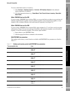
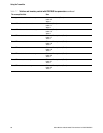
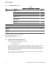
Table 8-1 Configuration map
Method
Topic Subtopic ProLink II PROFIBUS host
(1)
Display Section
Volume flow
measurement for gas
✓✓ 8.2
Cutoffs ✓✓ 8.3
Damping ✓✓ 8.4
Flow direction ✓✓ 8.5
Events ✓✓ 8.6
Slug flow ✓✓ 8.7
Status alarm severity ✓✓ 8.8
Display
(2)
Update period ✓✓ ✓8.9.1
Display language ✓✓ ✓8.9.2
Display variables and
precision
✓✓ 8.9.3
LCD panel backlight ✓✓ 8.9.4
Totalizer start/stop ✓✓ ✓8.9.5
Totalizer reset ✓✓ ✓
Auto scroll ✓✓ ✓
Scroll rate ✓✓ ✓
Offline menu ✓✓ ✓
Password ✓✓ ✓
Alarm menu ✓✓ ✓
Ack all ✓✓ ✓