


Configuration and Use Manual 127
Troubleshooting
Measurement Performance DefaultsTroubleshootingCompensation
11.10 Simulation mode
Simulation allows you to define arbitrary values for mass flow, temperature, and density. Simulation
mode has several uses:
• It can help determine if a problem is located in the transmitter or elsewhere in the system. For
example, signal oscillation or noise is a common occurrence. The source could be the
PROFIBUS host, the meter, improper grounding, or a number of other factors. By setting up
simulation to output a flat signal, you can determine the point at which the noise is introduced.
• It can be used to analyze system response or to tune the loop.
If simulation mode is active, the simulated values are stored in the same memory locations used for
process data from the sensor. Therefore, the simulated values will be used throughout transmitter
functioning. For example, simulation will affect:
• All mass flow, temperature, or density values shown on the display or reported via digital
communications
• The mass total and inventory values
• All volume calculations and data, including reported values, volume total, and volume
inventory
• All related values logged by Data Logger (a ProLink II utility)
Accordingly, do not enable simulation when your process cannot tolerate these effects, and be sure to
disable simulation when you have finished testing.
Note: Unlike actual mass flow and density values, the simulated values are not
temperature-compensated.
Simulation does not change any diagnostic values.
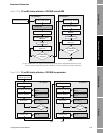
Simulation mode is available only via ProLink II. To set up simulation, refer to Figure C-3 and follow
the steps below:
1. Enable simulation mode.
2. For mass flow:
a. Specify the type of simulation you want: fixed value, sawtooth (triangular wave), or sine
wave.
b. Enter the required values.
• If you specified fixed value simulation, enter a fixed value.
• If you specified sawtooth or sine wave simulation, enter a minimum value, maximum
value, and wave period. Minimum and maximum values are entered in the current
measurement units; the wave period is entered in seconds.
3. Repeat Step 2 for temperature and density.
To use simulation mode for problem location, enable simulation mode and check the signal at various
points between the transmitter and the receiving device.