


Configuration and Use Manual 141
Troubleshooting
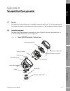
Measurement Performance DefaultsTroubleshootingCompensation
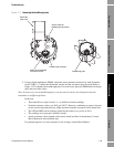
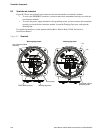
6. Using the DMM, check each pin as follows:
a. Check between the pin and the sensor case.
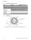
b. Check between the pin and other pins as described below:
• Drive + against all other pins except Drive –
• Drive – against all other pins except Drive +
• Left pickoff + against all other pins except Left pickoff –
• Left pickoff – against all other pins except Left pickoff +
• Right pickoff + against all other pins except Right pickoff –
• Right pickoff – against all other pins except Right pickoff +
• RTD + against all other pins except RTD – and LLC/RTD
• RTD – against all other pins except RTD + and LLC/RTD
• LLC/RTD against all other pins except RTD + and RTD –
With the DMM set to its highest range, there should be infinite resistance on each lead. If there
is any resistance at all, there is a short to case or a short between pins. See Table 11-8 for
possible causes and solutions. If the problem is not resolved, contact Micro Motion.
To return to normal operation:
1. Follow appropriate procedures to ensure that reconnecting the transmitter does not interfere
with existing measurement and control loops.
2. Reach inside the transmitter housing and install the transmitter’s sensor connection onto the
feedthrough:
a. Rotate the connector until it engages the pins.
b. Push down until the connector shoulder is flush with the feedthrough notch.
c. Replace the snap clip by sliding the clip tab over the connector shoulder (see the
instruction label on the component).
3. Replace the transmitter in the transmitter housing, and tighten the screws.
4. Reconnect the power wires, lower the Warning flap, and tighten the Warning flap screw.
5. Reconnect the PROFIBUS cable to the PROFIBUS terminals on the transmitter.
6. Plug the user interface module onto the transmitter. There are four possible positions; select
the position that is most convenient.
7. Tighten the user interface screws.
8. Replace the transmitter housing cover on the user interface module, and tighten the screws.
9. Power up the transmitter.
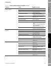
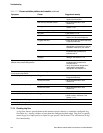
Table 11-8 Sensor and cable short to case causes and remedies
Cause Possible remedy
Moisture inside the transmitter housing • Make sure that the transmitter housing is dry and no corrosion is
present.
Liquid or moisture inside the sensor case • Contact Micro Motion.
Internally shorted feedthrough (sealed passage
for wiring from sensor to transmitter)
• Contact Micro Motion.