


96 Micro Motion
®
Model 2400S Transmitters for PROFIBUS-DP
Measurement Performance
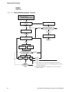
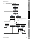
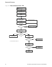
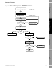
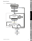
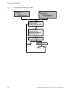
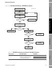
10.3.3 Running Smart Meter Verification
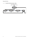
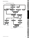
To run a Smart Meter Verification test:
• Using ProLink II, see Figure 10-5.
• Using the display, see Figures 10-6 and 10-7.
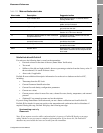
• Using a PROFIBUS host with the EDD, refer to Figure C-7 and follow the procedure
illustrated in Figure 10-8.
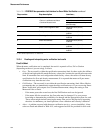
• Using PROFIBUS bus parameters, use the Diagnostic block (see Table D-4) and follow the
procedure illustrated in Figure 10-9.
Note: If you start a Smart Meter Verification test using ProLink II, the EDD, or PROFIBUS bus
parameters, and the outputs are set to Last Measured Value or Fault, the transmitter display shows
the following message:
SENSOR
VERFY/x%
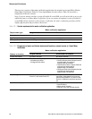
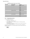
Table 10-3 PROFIBUS bus parameters interface for meter verification
Step number Step description Interface
(1)
(1) For detailed information, see Table D-4.
1 Set output state Diagnostic block (Slot 3)
Index 54
2 Set uncertainty limit Diagnostic block (Slot 3)
Index 55
3 Start/abort procedure Diagnostic block (Slot 3)
Index 53
4 Check current algorithm state Diagnostic block (Slot 3)
Index 56
5 Read percent complete Diagnostic block (Slot 3)
Index 61
6 Check algorithm abort state Diagnostic block (Slot 3)
Index 58
7 Check inlet stiffness Diagnostic block (Slot 3)
Index 59
8 Check outlet stiffness Diagnostic block (Slot 3)
Index 60
9 Read abort code Diagnostic block (Slot 3)
Index 57