128 Micro Motion
®
Model 2400S Transmitters for PROFIBUS-DP
Troubleshooting
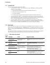
11.11 Transmitter LEDs
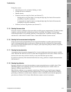
The user interface module includes three LEDs:
• A status LED. See Table 7-3 for information on status LED behavior. If the status LED
indicates an alarm condition:
a. View the alarm code using the procedures described in Section 7.6.
b. Identify the alarm (see Section 11.12).
c. Correct the condition.
d. If desired, acknowledge the alarm using the procedures described in Section 7.7.
• A network LED. See Table 7-1 for information on the behavior of the network LED. The
network LED indicates the state of the device on the network, and does not indicate device
status. Troubleshooting should focus on the network rather than the device.
• A software address LED. See Table 7-2 for information on the behavior of the software
address LED. You may need to set the node address for the Model 2400S DP transmitter, or
you may need to configure the PROFIBUS host to use the existing node address.
11.12 Status alarms
Status alarm codes are reported on the LCD panel (for transmitters that have displays), and status
alarms can be viewed with ProLink II or a PROFIBUS host. All possible status alarms are listed in
Table 11-2, along with the PROFIBUS host or ProLink II message, possible causes, and suggested
remedies.
You may find it useful to acknowledge all alarms before beginning the troubleshooting procedures.
This will remove inactive alarms from the list and allow you to focus on active alarms.
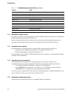
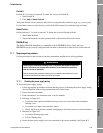
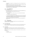
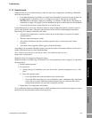
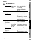
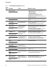
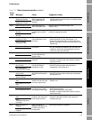
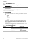
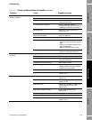
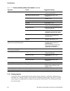
Table 11-2 Status alarms and remedies
Alarm
code Message
(1)
Cause Suggested remedy
A001 EEprom Checksum Error
(Core Processor)
An uncorrectable
checksum mismatch has
been detected
• Cycle power to the flowmeter.
• The flowmeter might need service. Contact Micro
Motion.
(E)EPROM Checksum
Error (CP)
A002 RAM Test Error (Core
Processor)
ROM checksum error or a
RAM location cannot be
written to
• Cycle power to the flowmeter.
• The flowmeter might need service. Contact Micro
Motion.
RAM Error (CP)
A003 Sensor Not Responding
(No Tube Interrupt)
Continuity failure of drive
circuit, LPO, or RPO, or
LPO-RPO mismatch when
driving
• Check for slug flow. See Section 11.14.
• Check the test points. See Section 11.20.
• Check the sensor circuitry. See Section 11.21.
• Check sensor tubes for plugging.
• If the problem persists, contact Micro Motion.
Sensor Failure
A004 Temperature sensor out
of range
Combination of A016 and
A017
• Check the sensor RTD circuitry. See Section 11.21.
• Verify that process temperature is within range of
sensor and transmitter.
• If the problem persists, contact Micro Motion.
Temperature Sensor
Failure


