


148 Micro Motion
®
Model 2400S Transmitters for PROFIBUS-DP
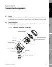
Transmitter Components
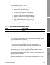
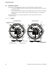
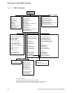
B.3 Terminals and connectors
Figure B-2 shows the terminals and connectors that are beneath the user interface module:
• To access the PROFIBUS connector, you must remove the transmitter housing cover and the
user interface module.
• To access the power supply terminals or the grounding screw, you must remove the transmitter
housing cover and the user interface module, loosen the Warning flap screw, and open the
Warning flap.
For detailed instructions, see the manual entitled Micro Motion Model 2400S Transmitters:
Installation Manual.
Figure B-2 Terminals
+ (L)
– (N)
Warning flap screw
PROFIBUS terminals
Warning flap closed Warning flap open
User interface module
connector
Warning flap
Transmitter internal
grounding screw