


Configuration and Use Manual 139
Troubleshooting
Measurement Performance DefaultsTroubleshootingCompensation
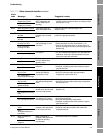
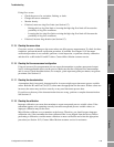
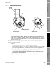
Figure 11-1 Accessing the feedthrough pins
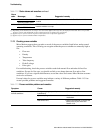
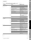
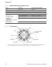
5. Using a digital multimeter (DMM), check the sensor internal resistances for each flowmeter
circuit. Table 11-7 defines the flowmeter circuits and the resistance range for each. Refer to
Figure 11-2 to identify the feedthrough pins. For each circuit, place the DMM leads on the pin
pairs and record the values.
Note: In order to access all feedthrough pins, you may need to remove the clamp and rotate the
transmitter to a different position.
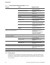
In this test:
• There should be no open circuits, i.e., no infinite resistance readings.
• Nominal resistance values vary 40% per 100 °C. However, confirming an open or shorted
circuit is more important than any slight deviation from the resistance values shown here.
• The LPO and RPO circuit readings should be the same or very close (± 10%).
• The readings across pin pairs should be steady.
• Actual resistance values depend on the sensor model and date of manufacture. Contact
Micro Motion for more detailed data.
If a problem appears, or if any resistance is out of range, contact Micro Motion.
Transmitter
(side view)
Sensor cable for
feedthrough connection
Feedthrough connector
Snap clip (assembled)
Pull tab to remove
Feedthrough pins