


Configuration and Use Manual 83
Pressure Compensation and External Temperature Compensation
Measurement Performance DefaultsTroubleshootingCompensation
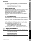
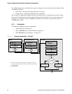
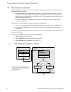
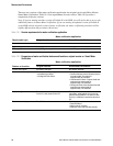
Figure 9-2 Pressure compensation – PROFIBUS host with the EDD
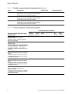
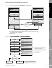
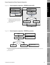
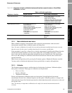
Figure 9-3 Pressure compensation – PROFIBUS bus parameters
Enter Pressure correction factor
for flow
Enter Pressure correction factor
for density
Enter Flow calibration pressure
Set up output module
(2)
Enter External Pressure Input
Enable Pressure Compensation
Select Pressure unit
(1)
Yes
MMI Coriolis Flow >
Pressure >
Pressure Configuration
MMI Coriolis Flow >
Pressure >
Pressure Compensation
Transfer
Transfer
Done
Use static
pressure value?
Transfer
No
(1) Pressure measurement unit must be configured to match pressure unit used by external device
or static pressure value. See Section 6.3.
(2) See Section 9.4.
Enable
Set pressure unit
Block: Calibration (Slot 2)
(1)
Index 36
Configure pressure
correction factor for flow
Block: Calibration (Slot 2)
Index 38
(2)
Block: Calibration (Slot 2)
Index 39
Configure pressure
correction factor for density
Block: Calibration (Slot 2)
Index 40
Configure flow calibration
pressure
Block: Calibration (Slot 2)
Index 41
Yes
Use static
pressure value?
No
Set up output
module
(3)
Block: Calibration (Slot 2)
Index 37
Set static value
(1) See Table D-3 for more information
about the bus parameters.
(2) Pressure measurement unit must be
configured to match pressure unit used
by external device or static pressure
value. See Section 6.3.
(3) See Section 9.4.