


54 Micro Motion
®
Model 2400S Transmitters for PROFIBUS-DP
Optional Configuration
7. Click Next. The calculated standard density value is displayed.
• If the value is correct, click
Finish. The value will be written to transmitter configuration.
• If the value is not correct, click
Back and modify input values as required.
Note: The Gas Wizard displays density, temperature, and pressure in the configured units. If required,
you can configure the transmitter to use different units. See Section 6.3.
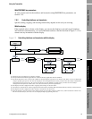
8.2.2 Using a PROFIBUS host with the EDD
To configure volume flow measurement for gas using a PROFIBUS host with the EDD:
1. Referring to Figure C-8:
a. Enable GSV.
b. Send the command to the transmitter.
c. Configure
Gas density value, GSV flow units, GSV total units, and GSV cutoff as
desired.
2. Send the command to the transmitter.
8.2.3 Using PROFIBUS bus parameters
To configure volume flow measurement for gas using PROFIBUS bus parameters:
1. Referring to the Measurement block (Table D-2):
a. Enable gas standard volume measurement (Index 33).
b. Set other gas measurement parameters as desired (Indices 34, 38, and 40).
2. Send the command to the transmitter.
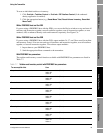
8.3 Configuring cutoffs
Cutoffs are user-defined values below which the transmitter reports a value of zero for the specified
process variable. Cutoffs can be set for mass flow, volume flow, gas standard volume flow, and
density.
See Table 8-2 for cutoff default values and related information. See Section 8.3.1 for information on
how the cutoffs interact with other transmitter measurements.
To configure cutoffs:
• Using ProLink II, see Figure C-2.
• Using a PROFIBUS host with the EDD, see Figure C-8.
• Using PROFIBUS bus parameters, use the Measurement block (see Table D-2), Indices 18, 19,
20, and 40.
Note: This functionality cannot be configured via the display menus.