


72 Micro Motion
®
Model 2400S Transmitters for PROFIBUS-DP
Optional Configuration
To configure digital communications fault action:
• Using ProLink II, see Figure C-2.
• Using a PROFIBUS host with the EDD, see Figure C-9.
• Using PROFIBUS bus parameters, use the Diagnostic block (see Table D-4), Index 18.
Note: This functionality cannot be configured via the display menus.
Note: Digital communications fault action is affected by the configured fault timeout. See
Section 8.10.8.
8.10.8 Fault timeout
By default, the transmitter activates the digital communications fault action as soon as the fault is
detected. The fault timeout (last measured value timeout) allows you to delay the digital
communications fault action for a specified interval, for certain faults only. During the fault timeout
period, digital communications reports the last measured value.
Note: The fault timeout applies only to the digital communications fault action. The “alarm active”
status bit is set as soon as the fault is detected (all alarm severity levels), and the “alarm active”
record is written to history immediately (Fault and Informational alarms only). For more information
on alarm handling, see Section 7.7. For more information on alarm severity, see Section 8.8.
The fault timeout applies only to specific faults. Other faults are reported immediately, regardless of
the fault timeout setting. For information on which faults are affected by the fault timeout, see
Table 8-8.
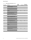
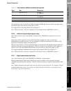
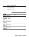
Table 8-12 Digital communications fault action options
Option
DefinitionProLink II label EDD label
Upscale Upscale • Process variables indicate that the value is greater than the
upper sensor limit.
• Totalizers stop incrementing.
Downscale Downscale • Process variables indicate that the value is less than the
lower sensor limit.
• Totalizers stop incrementing.
Zero IntZero-All 0 • Flow rate variables go to the value that represents zero
flow. Density is reported as zero.
• Temperature is reported as 0 °C, or the equivalent if other
units are used (e.g., 32 °F).
• Totalizers stop incrementing.
Not-A-Number (NAN) Not-a-Number • Process variables report IEEE NAN.
• Drive gain is reported as measured.
• Modbus scaled integers are reported as Max Int.
• Totalizers stop incrementing.
Flow to Zero IntZero-Flow 0 • Flow rate variables go to the value that represents zero
flow;
• Other process variables are reported as measured.
• Totalizers stop incrementing.
None (default) None • Process variables are reported as measured.
• Totalizers increment if they are running.