


102 Micro Motion
®
Model 2400S Transmitters for PROFIBUS-DP
Measurement Performance
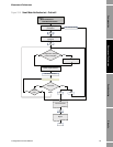
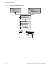
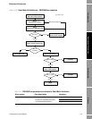
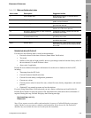
10.3.4 Reading and interpreting meter verification test results
Pass/Fail/Abort
When the meter verification test is completed, the result is reported as Pass, Fail or Caution
(depending on the tool you are using), or Abort:
• Pass – The test result is within the specification uncertainty limit. In other words, the stiffness
of the left and right pickoffs match the factory values plus or minus the specification uncertain
limit. If transmitter zero and configuration match factory values, the sensor will meet factory
specifications for flow and density measurement. It is expected that meters will pass meter
verification every time the test is run.
• Fail/Caution – The test result is not within the specification uncertainty limit. Micro Motion
recommends that you immediately repeat the meter verification test. If you were using Smart
Meter Verification, with outputs set to Continue Measurement, change the setting to Last
Measured Value or Fault.
- If the meter passes the second test, the first Fail/Caution result can be ignored.
- If the meter fails the second test, the flow tubes may be damaged. Use your process
knowledge to determine the possibilities for damage and the appropriate actions for each.
These actions might include removing the meter from service and physically inspecting
the tubes. At minimum, you should perform a flow validation and a density calibration.
• Abort – A problem occurred with the meter verification test (e.g., process instability). Abort
codes are listed and defined in Table 10-5, and suggested actions are provided for each code.
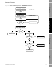
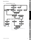
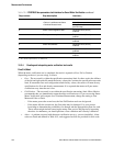
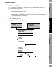
2 Start/abort test Diagnostic block (Slot 3)
• Fault or Last Measured Value Index 53
• Continue Measurement Not applicable (test started by
previous step)
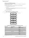
3 Check current algorithm state Diagnostic block (Slot 3)
Index 56
4 Read percent complete Diagnostic block (Slot 3)
Index 61
5 Check algorithm abort state Diagnostic block (Slot 3)
Index 58
6 Check inlet stiffness Diagnostic block (Slot 3)
Index 59
7 Check outlet stiffness Diagnostic block (Slot 3)
Index 60
8 Read abort code Diagnostic block (Slot 3)
Index 57
(1) For detailed information, see Table D-4
.
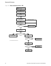
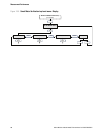
Table 10-4 PROFIBUS bus parameters test interface for Smart Meter Verification continued
Step number Step description Interface
(1)