


126 Micro Motion
®
Model 2400S Transmitters for PROFIBUS-DP
Troubleshooting
7. Verify that the power supply wires are making good contact, and are not clamped to the wire
insulation.
8. Inspect the voltage label on the inside of the field-wiring compartment. Verify that the voltage
supplied to the transmitter matches the voltage specified on the label.
9. Use a voltmeter to test the voltage at the transmitter’s power supply terminals. Verify that it is
within the specified limits. For DC power, you may need to size the cable. See your transmitter
installation manual for power supply requirements.
11.7.2 Checking PROFIBUS wiring
To check the PROFIBUS wiring:
1. Follow appropriate procedures to ensure that the process of checking the PROFIBUS wiring
does not interfere with existing measurement and control loops.
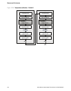
2. Referring to Figure B-1:
a. Loosen the four captive transmitter housing cover screws and remove the transmitter
housing cover.
b. Loosen the two captive user interface screws.
c. Gently lift the user interface module, disengaging it from the connector on the transmitter.
3. Visually inspect the PROFIBUS cable and wiring. Ensure that the wires are inserted into the
correct terminals (see Figure B-2), contact is good at both ends, the cable is not crimped, and
the cable covering is intact. Replace the cable if appropriate.
4. Verify that the internal termination resistor switch is set correctly for your installation. See
Figure 3-1 or 3-2.
11.7.3 Checking grounding
The sensor / transmitter assembly must be grounded. See your sensor installation manual for
grounding requirements and instructions.
11.8 Zero or calibration failure
If a zero or calibration procedure fails, the transmitter will send a status alarm indicating the cause of
failure. See Section 11.12 for specific remedies for status alarms indicating calibration failure.
11.9 Fault conditions
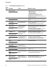
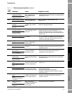
If a fault is reported, determine the exact nature of the fault by checking the status alarms (see
Section 7.6). Once you have identified the status alarm(s) associated with the fault condition, refer to
Section 11.12.
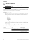
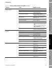
Some fault conditions can be corrected by cycling power to the transmitter. A power cycle can clear
the following:
• Zero failure
• Stopped internal totalizer