


Configuration and Use Manual 55
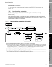
Optional Configuration
Required Configuration Optional ConfigurationUsing the TransmitterUsing a PROFIBUS Host Required Configuration Optional ConfigurationUsing the TransmitterUsing a PROFIBUS Host Required Configuration Optional ConfigurationUsing the TransmitterUsing a PROFIBUS Host Required Configuration Optional ConfigurationUsing the TransmitterUsing a PROFIBUS Host
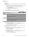
8.3.1 Cutoffs and volume flow
If liquid volume flow is enabled:
• The density cutoff is applied to the volume flow calculation. Accordingly, if the density drops
below its configured cutoff value, the volume flow rate will go to zero.
• The mass flow cutoff is not applied to the volume flow calculation. Even if the mass flow
drops below the cutoff, and therefore the mass flow indicators go to zero, the volume flow rate
will be calculated from the actual mass flow process variable.
If gas standard volume flow is enabled, neither the mass flow cutoff nor the density cutoff is applied
to the volume flow calculation.
8.4 Configuring the damping values
A damping value is a period of time, in seconds, over which the process variable value will change to
reflect 63% of the change in the actual process. Damping helps the transmitter smooth out small,
rapid measurement fluctuations.
• A high damping value makes the output appear to be smoother because the output must change
slowly.
• A low damping value makes the output appear to be more erratic because the output changes
more quickly.
Damping can be configured for flow, density, and temperature.
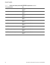
When you specify a new damping value, it is automatically rounded down to the nearest valid
damping value. Valid damping values are listed in Table 8-3.
Note: For gas applications, Micro Motion recommends a minimum flow damping value of 2.56.
Before setting the damping values, review Section 8.4.1 for information on how the damping values
affect other transmitter measurements.
To configure damping values:
• Using ProLink II, see Figure C-2.
• Using a PROFIBUS host with the EDD, see Figure C-8.
• Using PROFIBUS bus parameters, use the Measurement block (see Table D-2), Indices 12, 13,
and 14.
Note: This functionality cannot be configured via the display menus.
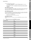
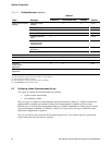
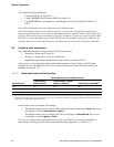
Table 8-2 Cutoff default values
Cutoff type Default Comments
Mass flow 0.0 g/s Recommended setting: 5% of the sensor’s rated maximum flowrate
Volume flow 0.0 L/s Limit: the sensor’s flow calibration factor in liters per second, multiplied by 0.2
Gas standard volume
flow
0.0 SCFM No limit
Density 0.2 g/cm
3
Range: 0.0–0.5 g/cm
3