Configuration and Use Manual 69
Optional Configuration
Required Configuration Optional ConfigurationUsing the TransmitterUsing a PROFIBUS Host Required Configuration Optional ConfigurationUsing the TransmitterUsing a PROFIBUS Host Required Configuration Optional ConfigurationUsing the TransmitterUsing a PROFIBUS Host Required Configuration Optional ConfigurationUsing the TransmitterUsing a PROFIBUS Host
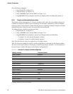
To set the node address with address switches:
1. Remove the transmitter housing cover as described in Section 3.3.
2. Identify the three address switches on the user interface module of your transmitter (see
Figure 3-1 or Figure 3-2).
3. For each switch, insert a small blade into the slot to rotate the arrow to the desired position. For
example, to set the node address to
60:
a. Rotate the arrow in the left switch to point to the digit
0.
b. Rotate the arrow in the center switch to point to the digit
6.
c. Rotate the arrow in the right switch to point to the digit
0.
4. Power-cycle the transmitter. At this point, the new node address is recognized by the
transmitter, but not the host. You must update the host configuration for the new address.
To set the node address with software:
1. Ensure that the transmitter is in software addressing mode (software address LED is red or
green). If it is, skip this step and go to Step 2. If it is currently in hardware addressing mode
(software address LED is off):
a. Set the address switches to
126 or higher.
b. Power-cycle the transmitter. At this point, the transmitter enters software addressing mode,
and the software address LED is red.
2. Send a Set Slave Address telegram from the host. It is not necessary to power-cycle the
transmitter. At this point, the new node address is recognized by both the transmitter and the
host, and the software address LED is green.
To return the node address to
126 (sometimes required for maintenance):
1. Because a Set Slave Address telegram cannot specify a node address of
126, you must set this
address via the address switches. If the transmitter is currently in hardware addressing mode
(software address LED is off), skip this step and go to Step 2. If it is currently in software
addressing mode (software address LED is red or green), switch to hardware addressing mode
as follows:
a. Set the address switches to any value between
0 and 125 (e.g., 100).
b. Power-cycle the transmitter. The transmitter enters hardware addressing mode, and the
software address LED is off.
2. Set the address switches to
126.
3. Power-cycle the transmitter.
8.10.2 IrDA port usage
The IrDA port on the display can be enabled or disabled. If enabled, it can be set for read-only or
read/write.
To enable or disable the IrDA port:
• Using ProLink II, see Figure C-2.
• Using the display menus, see Figure C-15.
• Using a PROFIBUS host with the EDD, see Figure C-10.
• Using PROFIBUS bus parameters, use the Local Display block (see Table D-6), Index 34.


