


Configuration and Use Manual 119
Measurement Performance
Measurement Performance DefaultsTroubleshootingCompensation
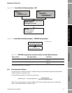
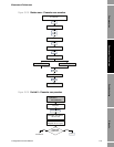
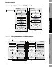
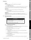
Figure 10-23 D1 and D2 density calibration – PROFIBUS host with EDD
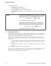
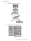
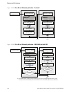
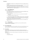
Figure 10-24 D1 and D2 density calibration – PROFIBUS bus parameters
D1 = Density of D1 fluid
D1 calibration
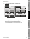
Close shutoff valve
downstream from sensor
Fill sensor with D1 fluid Fill sensor with D2 fluid
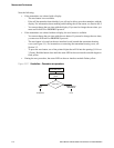
No
D2 calibration
No
Device >
Density cal
D1 calibration
in progress?
Check status
Alarm Five
Yes
Check status
Alarm Five
D2 calibration
in progress?
Yes
Done
(1)
Transfer
Transfer
Do Density Cal – Point 1 =
Start Cal
D2 = Density of D2 fluid
Do Density Cal – Point 2 =
Start Cal
(1) K1 and K2 values are displayed in the Density section of the Configuration Parameters menu.
You may need to reload values from the transmitter to see the results of the density calibration.
Enter density of D1 fluid
Monitor status
D1 calibration
Close shutoff valve
downstream from sensor
Fill sensor with D1 fluid
Block: Calibration (Slot 2)
Index 11
Start D1 calibration
Block: Calibration (Slot 2)
Index 21
Block: Diagnostic (Slot 3)
Index 14, Bit 14
Bit 14 0ff?No
Enter density of D2 fluid
Monitor status
D2 calibration
Fill sensor with D2 fluid
Block: Calibration (Slot 2)
Index 12
Start D2 calibration
Block: Calibration (Slot 2)
Index 22
Block: Diagnostic (Slot 3)
Index 14, Bit 13
Bit 13 0ff?No
Check K1 value
Block: Diagnostic (Slot 3)
Index 16
Yes
Check K2 value
Block: Diagnostic (Slot 3)
Index 17
Yes
Done Done