


82 Micro Motion
®
Model 2400S Transmitters for PROFIBUS-DP
Pressure Compensation and External Temperature Compensation
Two additional pressure correction factors may be configured: one for flow and one for density. These
are defined as follows:
• Flow factor – the percent change in the flow rate per psi
• Density factor – the change in fluid density, in g/cm
3
/psi
Not all sensors or applications require pressure correction factors. For the pressure correction values
to be used, obtain the pressure effect values from the product data sheet for your sensor, then reverse
the signs (e.g., if the flow factor is 0.000004 % per PSI, enter a pressure correction flow factor of
–0.000004 % per PSI).
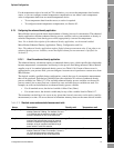
9.2.3 Configuration
To enable and configure pressure compensation:
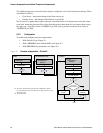
• With ProLink II, see Figure 9-1.
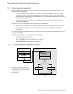
• With a PROFIBUS host with the EDD, see Figure 9-2.
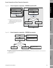
• With PROFIBUS bus parameters, see Figure 9-3.
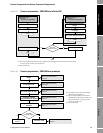
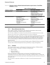
Figure 9-1 Pressure compensation – ProLink II
Enter Flow factor
Configure
Enter Density factor
Enter Cal pressure
Set up output
module
(2)
Enter External
Pressure
Enable External Pressure
Compensation
Enable
Apply
Enter Pressure units
Set measurement unit
(1)
Yes
Done
Apply
View >
Preferences
ProLink >
Configuration >
Pressure
ProLink >
Configuration >
Pressure
Apply
Apply
Use static
pressure value?
No
(1) Pressure measurement unit must be configured to match
pressure unit used by external device or static pressure value.
See Section 6.3.
(2) See Section 9.4.