


Configuration and Use Manual 19
Connecting with ProLink II or Pocket ProLink Software
Startup Using ProLink IITransmitter User InterfaceBefore You Begin Startup Using ProLink IITransmitter User InterfaceBefore You Begin Startup Using ProLink IITransmitter User InterfaceBefore You Begin Startup Using ProLink IITransmitter User InterfaceBefore You Begin
4.4.3 Making the connection
To connect to the service port:
1. If you are using the IrDA port:
a. Ensure that the IrDA port is enabled (see Section 8.10.2).
b. Ensure that there is no connection via the service port clips.
Note: Connections via the service port clips have priority over connections via the IrDA port. If you
are currently connected to the service port clips, you will not be able to connect via the IrDA port.
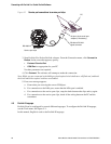
c. Position the IrDA device for communication with the IrDA port (see Figure 3-2). You do
not need to remove the transmitter housing cover.
Note: The IrDA port is typically used with Pocket ProLink. To use the IrDA port with ProLink II, a
special device is required; the IrDA port built into many laptop PCs is not supported. For more
information on using the IrDA port with ProLink II, contact Micro Motion customer service.
2. If you are using the service port clips:
a. Attach the signal converter to the serial or USB port of your PC, using the appropriate
connectors or adapters (e.g., a 25-pin to 9-pin adapter or a USB connector).
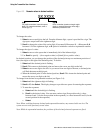
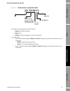
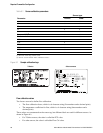
b. Remove the transmitter housing cover from the transmitter (see Section 3.3), then connect
the signal converter leads to the service port clips. See Figure 4-1.
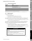
Table 4-1 Service port auto-detection limits
Parameter Option
Protocol Modbus ASCII or Modbus RTU
(1)
(1) Service port support for Modbus ASCII may be disabled. See Section 8.10.4.
Address Responds to both:
• Service port address (111)
• Configured Modbus address (default=1)
(2)
(2) See Section 8.10.3 for information on configuring the Modbus address.
Baud rate
(3)
(3) This is the baud rate between the service port and the connecting program. It is not the PROFIBUS DP baud rate.
Standard rates between 1200 and 38,400
Stop bits 1, 2
Parity Even, odd, none
WARNING
Removing the transmitter housing cover in a hazardous area can cause an
explosion.
Because the transmitter housing cover must be removed to connect to the service
port clips, the service port clips should be used only for temporary connections, for
example, for configuration or troubleshooting purposes.
When the transmitter is in an explosive atmosphere, use a different method to
connect to your transmitter.