68 Micro Motion
®
Model 2400S Transmitters for PROFIBUS-DP
Optional Configuration
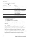
Note the following:
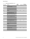
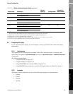
• If you use the display to disable access to the off-line menu, the off-line menu will disappear
as soon as you exit the menu system. If you want to re-enable access, you must use a different
method (e.g., ProLink II or a PROFIBUS host with the EDD).
• Scroll Rate is used to control the speed of scrolling when Auto Scroll is enabled. Scroll Rate
defines how long each display variable (see Section 8.9.3) will be shown on the display. The
time period is defined in seconds; e.g., if Scroll Rate is set to 10, each display variable will be
shown on the display for 10 seconds.
• The off-line password prevents unauthorized users from gaining access to the off-line menu.
The password can contain up to four numbers.
• If you are using the display to configure the display:
- You must enable Auto Scroll before you can configure Scroll Rate.
- You must enable the off-line password before you can configure the password.
8.10 Configuring digital communications
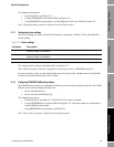
The digital communications parameters control how the transmitter will communicate using digital
communications. The following digital communications parameters can be configured:
• PROFIBUS-DP node address
• IrDA port usage
• Modbus address
• Modbus ASCII support
• Floating-point byte order
• Additional communications response delay
• Digital communications fault action
• Fault timeout
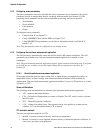
8.10.1 PROFIBUS-DP node address
The PROFIBUS-DP node address can be set with the address switches on the device (hardware
addressing mode) or with a PROFIBUS host.
Note: You cannot set the node address from ProLink II or the display.
The transmitter operates in either hardware addressing mode or software addressing mode:
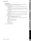
• In hardware addressing mode, the address switches are set to a value between
0 and 126, and
the position of the address switches determines the actual node address. The software address
LED on the face of the transmitter is off (see Figure 3-1 or Figure 3-2).
• In software addressing mode, the address switches are set to
126 or greater, and the node
address is set via a Set Slave Address telegram from the host. The position of the address
switches does not necessarily match the actual node address. The software address LED is
either red or green:
- Red – the transmitter has not received a Set Slave Address telegram.
- Green – the transmitter has received a Set Slave Address telegram and recognized the
address.
The default node address for the Model 2400S DP transmitter is
126, which allows either hardware
addressing or software addressing.


