


118 Micro Motion
®
Model 2400S Transmitters for PROFIBUS-DP
Measurement Performance
For D3 density calibration, the D3 fluid must meet the following requirements:
• Minimum density of 0.6 g/cm
3
• Minimum difference of 0.1 g/cm
3
between the density of the D3 fluid and the density of water.
The density of the D3 fluid may be either greater or less than the density of water
For D4 density calibration, the D4 fluid must meet the following requirements:
• Minimum density of 0.6 g/cm
3
• Minimum difference of 0.1 g/cm
3
between the density of the D4 fluid and the density of the
D3 fluid. The density of the D4 fluid must be greater than the density of the D3 fluid
• Minimum difference of 0.1 g/cm
3
between the density of the D4 fluid and the density of water.
The density of the D4 fluid may be either greater or less than the density of water
10.6.2 Density calibration procedures
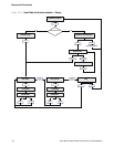
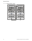
To perform a D1 and D2 density calibration:
• With ProLink II, see Figure 10-22.
• With a PROFIBUS host with the EDD, see Figure 10-23.
• With PROFIBUS bus parameters, see Figure 10-24.
To perform a D3 density calibration or a D3 and D4 density calibration:
• With ProLink II, see Figure 10-25.
• With a PROFIBUS host with the EDD, see Figure 10-26.
• With PROFIBUS bus parameters, see Figure 10-27.
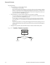
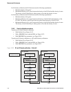
Figure 10-22 D1 and D2 density calibration – ProLink II
Enter density of D1 fluid
Calibration in Progress
light turns green
Calibration in Progress
light turns red
D1 calibration
Close shutoff valve
downstream from sensor
Fill sensor with D1 fluid Fill sensor with D2 fluid
Close
Enter density of D2 fluid
Calibration in Progress
light turns green
Calibration in Progress
light turns red
D2 calibration
Close
Done
Do Cal
Do Cal
ProLink Menu >
Calibration >
Density cal – Point 1
ProLink Menu >
Calibration >
Density cal – Point 2