


Configuration and Use Manual 7
Startup Using ProLink IITransmitter User InterfaceBefore You Begin
Chapter 2
Flowmeter Startup
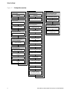
2.1 Overview
This chapter describes the following procedures:
• Setting the node address – see Section 2.2
• Bringing the flowmeter online – see Section 2.3
2.2 Setting the node address
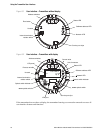
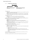
Three address switches are provided on the user interface module (see Figure 3-1 or Figure 3-2).
These switches are used to set a three-digit node address for the device:
• The leftmost switch sets the first digit.
• The center switch sets the second digit.
• The rightmost switch sets the third digit.
The default setting for the address switches is
126.
You can set the node address manually before bringing the device online, by rotating the address
switches to any value between
0 and 125. If the transmitter was powered on at the time the address
switches were set, it will not accept the new node address until you perform a power cycle.
If the transmitter is brought online with the switches set to
126:
• The device shows up at address
126 in the live list.
• You can set the node address programmatically by sending a Set Slave Address telegram from
the PROFIBUS host.
• You can set the node address manually by rotating the switches to any value between
0 and
125, then power-cycling the device.
For more information on setting the node address, see Section 8.10.1.
Note: It is not necessary to set the baud rate. because the Model 2400S DP transmitter automatically
detects and uses the DP segment baud rate.
2.3 Bringing the transmitter online
To bring the transmitter online:
1. Follow appropriate procedures to ensure that the process of configuring and commissioning
the Model 2400S DP transmitter does not interfere with existing measurement and control
loops.
2. Ensure that the PROFIBUS cable is connected to the transmitter as described in the transmitter
installation manual.
3. Ensure that all transmitter and sensor covers and seals are closed.