


140 Micro Motion
®
Model 2400S Transmitters for PROFIBUS-DP
Troubleshooting
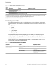
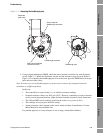
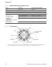
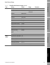
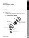
Figure 11-2 Feedthrough pins
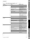
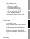
Table 11-7 Nominal resistance ranges for flowmeter circuits
Circuit Pin pairs Nominal resistance range
(1)
(1) Actual resistance values depend on the sensor model and date of manufacture. Contact Micro Motion for more detailed data.
Drive Drive + and – 8–1500 Ω
Left pickoff Left pickoff + and – 16–1000 Ω
Right pickoff Right pickoff + and – 16–1000 Ω
Flow tube temperature sensor RTD + and RTD – 100 Ω at 0 °C + 0.38675 Ω / °C
LLC/RTD
• T-Series sensors RTD – and composite RTD 300 Ω at 0 °C + 1.16025 Ω / °C
• CMF400 I.S. sensors RTD – and fixed resistor 39.7–42.2 Ω
• F300 sensors
• H300 sensors
• F025A, F050A, F100A sensors
• CMFS sensors
RTD – and fixed resistor 44.3–46.4 Ω
• All other sensors RTD – and LLC 0
Left pickoff –
Right pickoff –
Drive – Drive +
Right pickoff +
Left pickoff +
LLC / Composite RTD /
Fixed resistor
(1)
RTD +
(1) Functions as fixed resistor for the following sensors: F300, H300, F025A, F050A, F100A, CMF400 I.S., CMFS. Functions
as composite RTD for T-Series sensors. For all other sensors, functions as lead length compensator (LLC).
RTD –