


38 Micro Motion
®
Model 2400S Transmitters for PROFIBUS-DP
Using the Transmitter
7.4.5 With PROFIBUS bus parameters
To read process variable data with PROFIBUS bus parameters:
• For petroleum measurement process variables, use the API block (see Table D-7)
• For enhanced density process variables, use the Enhanced Density block (see Table D-8)
• For all other process variables, use the Measurement block (see Table D-2)
7.5 Using the LEDs
The user interface module provides three LEDs: a status LED, a network LED, and a software address
LED (see Figures 3-1 and 3-2).
• For transmitters with a display, the LEDs can be viewed with the transmitter housing cover in
place.
• For transmitters without a display, the transmitter housing cover must be removed to view the
LEDs (see Section 3.3).
For information on:
• Using the network LED, see Section 7.5.1.
• Using the software address LED, see Section 7.5.2.
• Using the status LED, see Section 7.6.1.
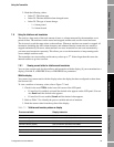
7.5.1 Using the network LED
Table 7-1 lists the different states of the network LED and defines each state.
7.5.2 Using the software address LED
Table 7-2 lists the different states of the software address LED and defines each state.
Table 7-1 Network LED states, definitions, and recommendations
Network LED state Definition Comments
Off Device not online The PROFIBUS-DP communication channel is not
connected to any host system. Check the host
configuration and the wiring, and retry the
connection.
Solid green Device online and connected The device is in data exchange with a Class 1
master or is being configured by a Class 2 master.
No action is required.
Flashing green Device online but not connected The device has detected the network baud rate, but
communication with a host has not been established.
Solid red Communication error Check for any of the following PROFIBUS
communication issues: Invalid Parameterization,
Invalid Configuration, Invalid Slot, Invalid Index,
Invalid C2 Acyclic Communication Initiate Telegram.