


Configuration and Use Manual 71
Optional Configuration
Required Configuration Optional ConfigurationUsing the TransmitterUsing a PROFIBUS Host Required Configuration Optional ConfigurationUsing the TransmitterUsing a PROFIBUS Host Required Configuration Optional ConfigurationUsing the TransmitterUsing a PROFIBUS Host Required Configuration Optional ConfigurationUsing the TransmitterUsing a PROFIBUS Host
The default byte order for the Model 2400S transmitter is 3–4 1–2. You may need to reset byte order
to match the byte order used by a remote host or PLC.
To configure byte order using ProLink II, see Figure C-2.
Note: This functionality cannot be configured via the display menus or PROFIBUS protocol.
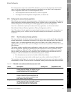
8.10.6 Additional communications response delay
Note: This parameter affects only Modbus communications. PROFIBUS communications are not
changed.
Some hosts or PLCs operate at slower speeds than the transmitter. In order to synchronize
communication with these devices, you can configure an additional time delay to be added to each
response the transmitter sends to the remote host.
The basic unit of delay is 2/3 of one character time, as calculated for the current serial port baud rate
setting and character transmission parameters. This basic delay unit is multiplied by the configured
value to arrive at the total additional time delay. You can specify a value in the range 1 to 255.
To configure additional communications response delay using ProLink II, see Figure C-2.
Note: This functionality cannot be configured via the display menus or PROFIBUS protocol.
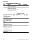
8.10.7 Digital communications fault action
Note: This parameter affects both PROFIBUS and Modbus communications.
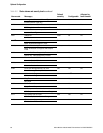
Digital communications fault action controls how process variables will be reported via digital
communications during fault conditions. Table 8-12 lists the options for digital communications fault
action.
Note: Digital communications fault action does not affect the alarm status bits. For example, if digital
communications fault action is set to None, the alarm status bits will still be set if an alarm occurs.
See Section 7.7 for more information.
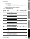
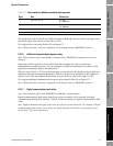
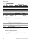
Table 8-11 Byte contents in Modbus commands and responses
Byte Bits Definitions
1 S E E E E E E E S = Sign
E = Exponent
2 E M M M M M M M E = Exponent
M = Mantissa
3 M M M M M M M M M = Mantissa
4 M M M M M M M M M = Mantissa