


Configuration and Use Manual 39
Using the Transmitter
Required Configuration Optional ConfigurationUsing the TransmitterUsing a PROFIBUS Host
7.6 Viewing transmitter status
You can view transmitter status using the status LED, ProLink II, a PROFIBUS host using the EDD,
or PROFIBUS bus parameters. Depending on the method chosen, different information is displayed.
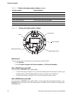
7.6.1 Using the status LED
The status LED shows transmitter status as described in Table 7-3. Note that the status LED does not
report event status or alarm status for alarms with severity level set to Ignore (see Section 8.8).
7.6.2 Using ProLink II
ProLink II provides a Status window that displays:
• Device (alarm) status
•Event status
• Assorted other transmitter data
7.6.3 Using a PROFIBUS host and the EDD
Status information is located in the View menu (see Figure C-5) and the Device menu (see Figures
C-6 and C-7). The View menu displays alarm status. The Device menu displays:
•Alarm status
•Event status
• Meter and core processor diagnostics
7.6.4 Using PROFIBUS bus parameters
Status information is located in the Diagnostic block (see Table D-4).
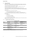
Table 7-2 Software address LED states, definitions, and recommendations
Software address LED state Definition
Off Device is in hardware addressing mode.
Solid red Device is in software addressing mode but address has not been set by host.
Solid green Device is in software addressing mode and address has been set by host.
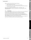
Table 7-3 Transmitter status LED
Status LED state Alarm priority Definition
Green No alarm Normal operating mode
Flashing yellow A104 alarm Zero or calibration in progress
Yellow Low severity (information) alarm • Alarm condition: will not cause measurement error
• Digital communications report process data
Red High severity (fault) alarm • Alarm condition: will cause measurement error
• Digital communications go to configured fault
action (see Section 8.10.7)