


28 Micro Motion
®
Model 2400S Transmitters for PROFIBUS-DP
Required Transmitter Configuration
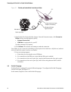
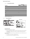
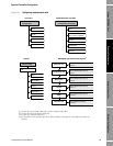
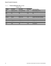
Figure 6-2 Characterizing the flowmeter
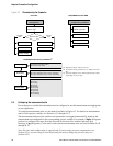
6.3 Configuring the measurement units
For each process variable, the transmitter must be configured to use the measurement unit appropriate
to your application.
To configure measurement units, see the menu flowcharts in Figure 6-3. For details on measurement
units for each process variable, see Sections 6.3.1 through 6.3.4.
The measurement units used for totalizers and inventories are assigned automatically, based on the
measurement unit configured for the corresponding process variable. For example, if
kg/hr (kilograms
per hour) is configured for mass flow, the unit used for the mass flow totalizer and mass flow
inventory is
kg (kilograms). Codes used for the totalizer measurement units are listed in Tables D-10
through D-12.
Note: Pressure unit configuration is required only if you are using pressure compensation (see
Section 9.2) or you are using the Gas Wizard and you need to change the pressure units (see
Section 8.2.1).
Device
· Sensor type
T Series Config
Straight
tube
Curved
tube
Sensor type?
ProLink >
Configuration
Flow
Density
Flow
Density
Sensor
· Sensor type code
T-Series
(1)
MMI Coriolis Flow >
Configuration parameters
Density
Flow
Sensor type
Flow values
Block: Device Information (Slot 4)
Index 8 (sensor type code)
Density values
(3)
Block: Calibration (Slot 2)
Index 16 (D1)
Index 17 (D2)
Index 18 (FD)
Index 26 (DTC)
Index 27 (FTG)
Index 28 (FFQ)
Index 29 (DTG)
Index 30 (DFQ1)
Index 31 (DFQ2)
Block: Calibration (Slot 2)
Index 4 (flow calibration factor, first six characters)
Index 5 (flow calibration factor, last four characters)
PROFIBUS host with EDDProLink II
PROFIBUS host with bus parameters
(2)
(1) Required only for T-Series sensors.
(2) For details on bus parameters, see Tables D-5 and
D-3.
(3) You will configure only a subset of the density values,
depending on sensor type.