


26 Micro Motion
®
Model 2400S Transmitters for PROFIBUS-DP
Required Transmitter Configuration
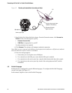
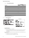
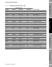
Figure 6-1 Sample calibration tags
Flow calibration values
Two factors are used to define flow calibration:
• The flow calibration factor, which is a 6-character string (five numbers and a decimal point)
• The temperature coefficient for flow, which is a 4-character string (three numbers and a
decimal point)
These values are concatenated on the sensor tag, but different labels are used for different sensors. As
shown in Figure 6-1:
• For T-Series sensors, the value is called the FCF value.
• For other sensors, the value is called the Flow Cal value.
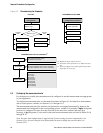
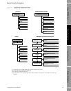
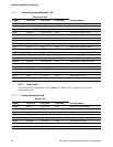
Table 6-1 Sensor calibration parameters
Parameter
Sensor type
T- Ser ie s Ot he r
K1 ✓✓
K2 ✓✓
FD ✓✓
D1 ✓✓
D2 ✓✓
Temp coeff (DT)
(1)
(1) On some sensor tags, shown as TC.
✓✓
Flowcal ✓
(2)
(2) See the section entitled “Flow calibration values.”
FCF ✓
FTG ✓
FFQ ✓
DTG ✓
DFQ1 ✓
DFQ2 ✓
Other sensors
19.0005.13
0.0010
0.9980
12502.000
14282.000
4.44000
310
12500142864.44
T-S eri es