Installation
4-47
Octel Overture 200/300 Serenade 3.0
PB60014–01
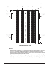
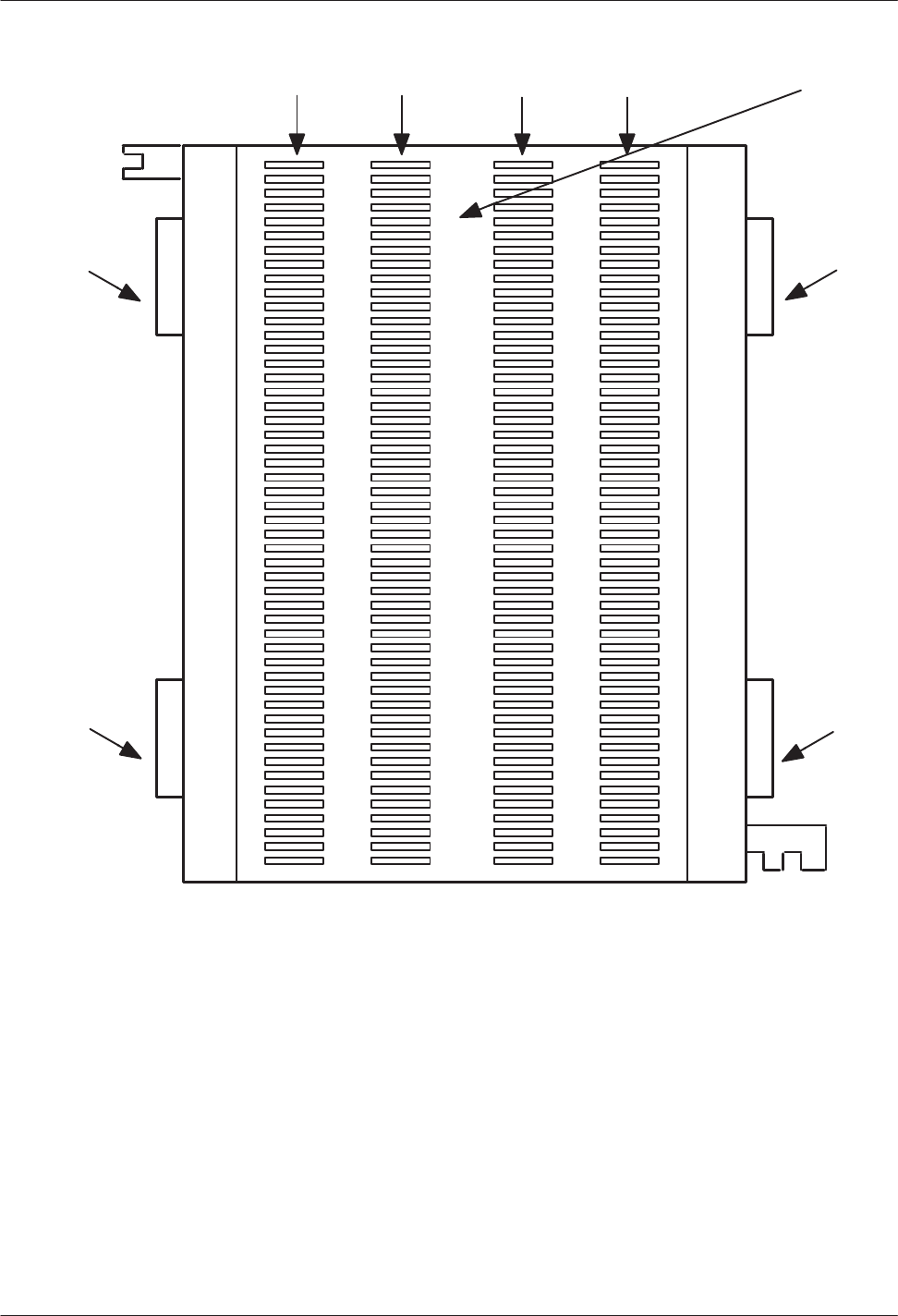
Figure 4-11
Connector Block
A B
C DColumn =
1
2
3
4
5
6
7
8
9
10
11
12
13
14
15
16
17
18
19
20
21
22
23
24
25
Pair
Number
Jack 3 (C)
to slot 3
Jack 4 (D)
to slot 4
Jack 1 (A)
Jack 2 (B)
to slot 2
To p
to slot 1
Wiring
In
most cases, the existing wiring is not consistent in its placement of the connections. To isolate faults
quickly
, it is recommended that the slots be connected in numerical order
, allowing for known or
anticipated expansion. At least, make sure that the slot and port numbers can be translated to extension
numbers that are meaningful to the servicing technician.
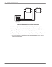
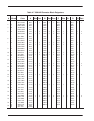
Figure 4-12 is an example of a 16-port message server that requires one connector block and four 25-pair
cables. From the rear of the cabinet, connect the first 25-pair cable from P1 to jack position 1 of the
66M4-4W connector block, or column A; connect the second 25-pair cable from P2 to jack position 2, or
column B; etc.


