Installation
4-41
Octel Overture 200/300 Serenade 3.0
PB60014–01
Preinstallation
Determine
whether the rack to be used is of a suitable size and strength to hold the Octel Overture 300.
At maximum configuration, the server can weigh as much as 220 pounds and might be too heavy for
some racks. Make sure that the rack is structurally sound before and after the server is installed. Remove
any rack casters, as they make the rack less stable. T
o increase stability further, you might need to bolt
the rack to the floor or provide some other means of support.
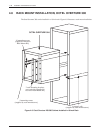
Obtain support rails from the rack manufacturer
. Install the rails in the rack to support the weight of the
server
. Unless the rack has threaded holes in vertical mounting rails, the rack manufacturer must also
provide speed nuts and rack-mounting screws for securing the front of the server to the rack.
If the Octel Overture 300 is currently in service, make sure that all cables connected to the back of the
server are long enough to reach the server when it is mounted in the rack.
The front and back of the rack must remain open to ensure proper air flow through the server
. Mount the
server low enough in the rack so that any service person can easily service the server while standing on
the floor
.
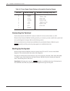
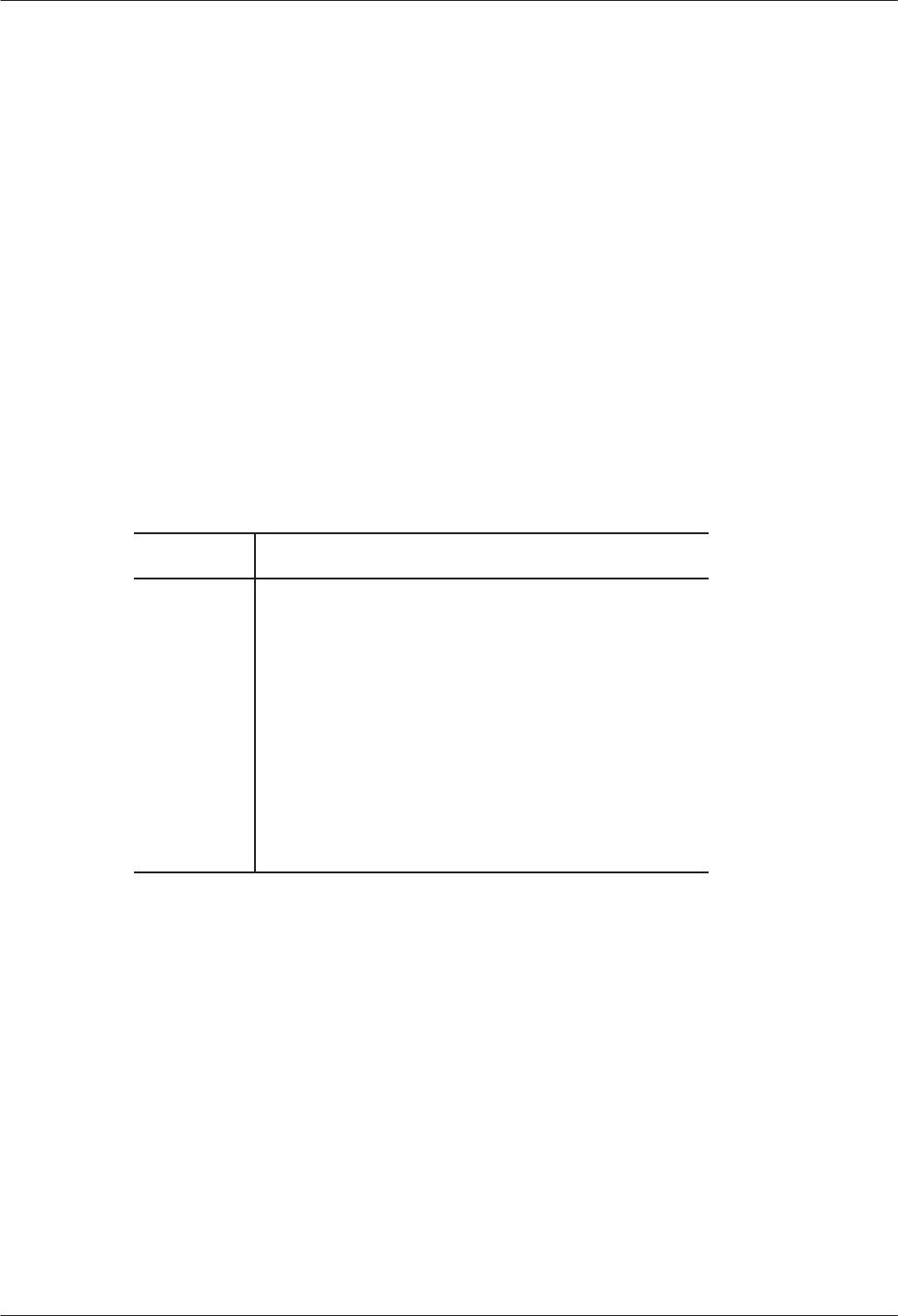
The following equipment and tools are required:
Quantity Description
1
Octel Overture 300 message server
1
Rack mount kit, Part No.
740-6036-001, which
includes two mounting brackets and 10 mounting
screws
1
19-inch rack
2
Support rails, rated for at least 220 pounds
8
Rack-mounting screws
8
Speed nuts, if required
1
Phillips screwdriver
Installation
Use the following steps to install the Octel Overture 300 in a rack:
1.
Open and remove the front door of the server
.
2.
Put on an antistatic wrist strap. Connect it to an unpainted portion of the cabinet.
3.
Make sure that the power to the Octel Overture 300 is turned OFF
.
4.
Remove the power
-supply unit, fan tray
, and all disk drives to reduce the weight of the cabinet and to
protect the disk drives from damage. Refer to the Hardware Replacement chapter
, Hardware
Removal section, for instructions about removing assemblies. Make sure to note the slot position of
all disk drives, because they must be replaced in the same slots. Y
ou do not need to remove PCAs in
slots A1 through A14.


