Installation
4-37
Octel Overture 200/300 Serenade 3.0
PB60014–01
4.7 OCTEL
OVERTURE 200/300 HARDW
ARE INST
ALLATION
The
physical installation of the message server begins by connecting the printer to the Octel Overture
200/300, applying power
, and observing the Octel Overture 200/300 self-test.
Powering Up
Connect
the Octel Overture 200/300 power cord to the dedicated power circuit and turn the cabinet power
switch to ON.
The LEDs on each circuit board are ON or OFF according to the following sequence after power up or
reset:
1.
Diagnostic Phase (red LED ON, green LED OFF)
After power up or reset, each circuit board executes its diagnostic self-test. While the self-test is
being performed, the red LED is ON and the green LED is OFF
. A diagnostic self-test can take up to
five minutes.
2.
Software Download Phase (red LED ON, green LED ON)
If a circuit board’
s diagnostic self-test is successful, the green LED is turned ON. If the green LED
does not come on within five minutes after power up or reset, replace the circuit board.
3.
Operational Phase (red LED OFF
, green LED ON)
The downloaded operational software turns OFF the red LED, indicating that the circuit board is
operational.
4.
Activity LED (yellow LED ON or OFF)
The yellow LED indicates activity. The meaning of the yellow LED is circuit board dependent.
Measuring d.c. Voltages
The
a.c. and d.c. wiring is prewired to connectors that are automatically engaged when the power supply
is installed. There are no power
-supply adjustments. Use a digital voltmeter to measure the system d.c.
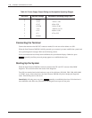
voltages at the voltage test points on the front edge of the CPU board. Measure between Test Point 1,
ground (use a common probe lead), and other test points to determine whether the voltages are in range.
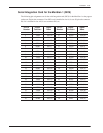
Refer to T
able 4-6; if any voltage is out of range, replace the power supply
.


