Teledyne API M100E Analyzer Operation Manual Operating Instructions
95
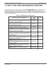
6.9. SETUP – DIAG: USING THE DIAGNOSTICS FUNCTIONS
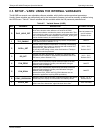
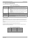
A series of diagnostic tools is grouped together under the SETUPMOREDIAG menu. As these parameters
are dependent on firmware revision (refer to Menu Tree, A-5, in Appendix A). The individual parameters,
however, are explained in more detail in the following section, indicated in Table 6-8. These tools can be used in
a variety of troubles
hooting and diagnostic procedures and are referred to in many places of the maintenance
and trouble-shooting sections.
Table 6-8: M100E Diagnostic (DIAG) Functions
DIAGNOSTIC FUNCTION AND MEANING
FRONT PANEL
MODE
INDICATOR
SECTION
SIGNAL I/O: Allows observation of all digital and analog signals
in the instrument. Allows certain digital signals such as valves
and heaters to be toggled ON and OFF.
DIAG I/O
6.9.2
ANALOG I/O: When entered, the analyzer performs an analog
output step test. This can be used to calibrate a chart recorder
or to test the analog output accuracy.
DIAG AOUT
6.9.3
ANALOG I/O CONFIGURATION: Analog input/output
parameters are available for viewing and configuration.
DIAG AIO
6.9.4
OPTIC TEST: When activated, the analyzer performs an optic
test, which turns on an LED located inside the sensor module
near the PMT (Fig. 10-15). This diagnostic tests the response of
the PMT without having to supply span gas.
DIAG OPTIC
6.9.5
ELECTRICAL TEST: When activated, the analyzer performs an
electric test, which generates a current intended to simulate the
PMT output to verify the signal handling and conditioning of the
PMT preamp board.
DIAG ELEC
6.9.6
LAMP CALIBRATION: The analyzer records the current
voltage output of the UV source reference detector. This value
is used by the CPU to calculate the lamp ratio used in
determining the SO
2
concentration
DIAG LAMP
6.9.7
PRESSURE CALIBRATION: The analyzer records the current
output of the sample gas pressure sensor. This value is used
by the CPU to compensate the SO
2
concentration when the
TPC feature is enabled.
DIAG PCAL
6.9.8
FLOW CALIBRATION: This function is used to calibrate the
gas flow output signals of sample gas and ozone supply. These
settings are retained when exiting DIAG.
DIAG FCAL
6.9.9
TEST CHAN OUTPUT: Configures the A4 analog output
channel.
DIAG TCHN
6.9.10
04515F DCN6048


