Teledyne API M100E Analyzer Operation Manual Theory Of Operation
243
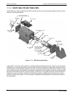
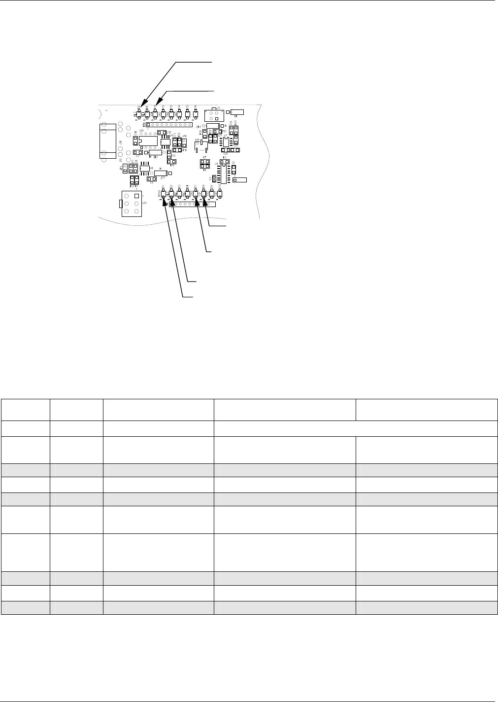
11.4.8. STATUS LEDS & WATCH DOG CIRCUITRY
Zero/Span and IZS Options
Sample/CAL Valve
IZS Option
Permeation Tube Heater
Dark Shutter
Sample Chamber Heater
I2C Watchdog LED
Zero/Span and IZS Options
Zero/Span Valve
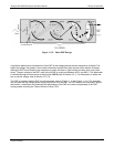
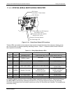
Figure 11-18: Relay Board Status LED Locations
Thirteen LEDs are located on the analyzer’s relay board to indicate the status of the analyzer’s heating zones
and valves as well as a general operating watchdog indicator. Table 11-1 shows the state of these LEDs and
their resp
ective functionality.
Table 11-1: Relay Board Status LED’s
LED COLOR FUNCTION STATUS WHEN LIT STATUS WHEN UNLIT
D1 RED Watchdog circuit
Cycles On/Off every 3 seconds under control of the CPU.
D2 YELLOW
Sample chamber
(RCELL) heater
HEATING NOT HEATING
D3, D4 YELLOW Unused N/A N/A
D5 YELLOW IZS heater (option) HEATING NOT HEATING
D6 YELLOW Unused N/A N/A
D7 GREEN Zero / Span Valve Valve open to Span Gas path
Valve open to Zero Gas
(normal state)
D8 GREEN Sample / Cal Valve
Valve open to
calibration gas path
Valve open to sample gas
inlet on rear panel
(normal state)
D9, D10 GREEN Unused N/A N/A
D11 GREEN UV Lamp Shutter Shutter open Shutter closed
D12-14 GREEN Unused N/A N/A
As a Safety measure, special circuitry on the Relay Board watches the status of LED D1. Should this LED ever
stay ON or OFF for 30 seconds, indicating that the CPU or I
2
C bus has stopped functioning, the Watchdog
Circuit will automatically shut of all valves as well as turn off the UV Source(s) and all heaters. The sample pump
will still be running.
04515F DCN6048


