


Getting Started Teledyne API M100E Analyzer Operation Manual
42
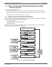
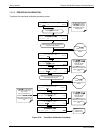
3.6. INITIAL CALIBRATION OF THE M100E
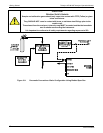
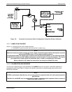
To perform the following calibration you must have sources for zero air and span gas available for input into the
sample port on the back of the analyzer. Refer to Section 3.4 for instructions for connecting the
se gas sources.
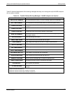
The initial calibration should be carried out using the same reporting range set up as used during the analyzer’s
factory calibration. This will allow you to compare your calibration results to the factory calibration as listed on
the Final Test and Validation Data Sheet, P/N 04551.
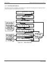
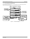
If both available iDAS parameters for a specific gas type are being reported via the instruments analog outputs
(e.g. CONC1 and CONC2 when the DUAL range mode is activated), separate calibrations should be carried out
for each parameter.
Use the LOW button when calibrating for CONC1 (equivalent to RANGE1).
Use the HIGH button when calibrating for CONC2 (equivalent to RANGE2).
Refer to the Configurable Analog Output Addendum, P/N 06270 for more information on the configurable analog
output reporting ranges
NOTE
The following procedure assumes that the instrument does not have any of the available Valve Options
installed.
Refer to Section 8.4 for instructions for calibrating instruments possessing valve options.
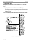
3.6.1. INTERFERENTS FOR MEASUREMENTS
It should be noted that the UV fluorescence method for detecting SO
2
is subject to interference from a number of
sources. The most common source of interference is from other gases that fluoresce in a similar fashion to SO
2
when exposed to UV Light such as Nitrogen Oxide (NO) and Poly-Nuclear Aromatics (PNA), of which certain
hydrocarbons such as meta-xylene and naphthalene are the most pervasive. The M100E has been successfully
tested for its ability to reject interference from most of these sources.
For a more detailed discussion of this topic, refer to Section 11.2.7.
04515F DCN6048