


Teledyne API M100E Analyzer Operation Manual Remote Operation and Advanced Features
139
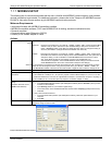
7.2. USING THE INTERNAL DATA ACQUISITION SYSTEM (IDAS)
The M100E analyzer contains a flexible and powerful, internal data acquisition system (iDAS) that enables the
analyzer to store concentration and calibration data as well as a host of diagnostic parameters. The iDAS of the
M100E can store up to about one million data points, which can, depending on individual configurations, cover
days, weeks or months of valuable measurements. The data are stored in non-volatile memory and are retained
even when the instrument is powered off. Data are stored in plain text format for easy retrieval and use in
common data analysis programs (such as spreadsheet-type programs).
The iDAS is designed to be flexible, users have full control over the type, length and reporting time of the data.
The iDAS permits users to access stored data through the instrument’s front panel or its communication ports.
Using APICOM, data can even be retrieved automatically to a remote computer for further processing.
The principal use of the iDAS is logging data for trend analysis and predictive diagnostics, which can assist in
identifying possible problems before they affect the functionality of the analyzer. The secondary use is for data
analysis, documentation and archival in electronic format.
To support the iDAS functionality, Teledyne API offers APICOM, a program that provides a visual interface for
remote or local setup, configuration and data retrieval of the iDAS. The APICOM manual, which is included with
the program, contains a more detailed description of the iDAS structure and configuration, which is briefly
described in this section.
The M100E is configured with a basic iDAS configuration, which is enabled by default. New data channels are
also enabled by default but each channel may be turned off for later or occasional use. Note that iDAS operation
is suspended while its configuration is edited through the front panel. To prevent such data loss, it is
recommended to use the APICOM graphical user interface for iDAS changes.
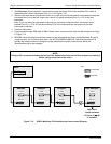
The green SAMPLE LED on the instrument front panel, which indicates the analyzer status, also indicates
certain aspects of the iDAS status:
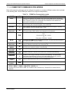
Table 7-5: Front Panel LED Status Indicators for iDAS
LED STATE IDAS STATUS
Off
System is in calibration mode. Data logging can be enabled or disabled for this mode.
Calibration data are typically stored at the end of calibration periods, concentration data
are typically not sampled, diagnostic data should be collected.
Blinking
Instrument is in hold-off mode, a short period after the system exits calibrations. IDAS
channels can be enabled or disabled for this period. Concentration data are typically
disabled whereas diagnostic should be collected.
On Sampling normally.
The iDAS can be disabled only by disabling or deleting its individual data channels.
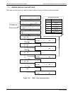
7.2.1. IDAS STRUCTURE
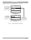
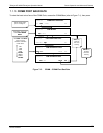
The iDAS is designed around the feature of a “record”. A record is a single data point of one parameter, stored in
one (or more) data channels and generated by one of several triggering event. The entire iDAS configuration is
stored in a script, which can be edited from the front panel or downloaded, edited and uploaded to the instrument
in form of a string of plain-text lines through the communication ports.
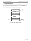
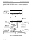
iDAS data are defined by the PARAMETER type and are stored through different triggering EVENTS in data
CHANNELS, which relate triggering events to data parameters and define certain operational functions related to
the recording and reporting of the data.
04515F DCN6048