


Teledyne API M100E Analyzer Operation Manual Theory Of Operation
229
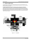
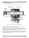
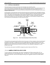
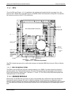
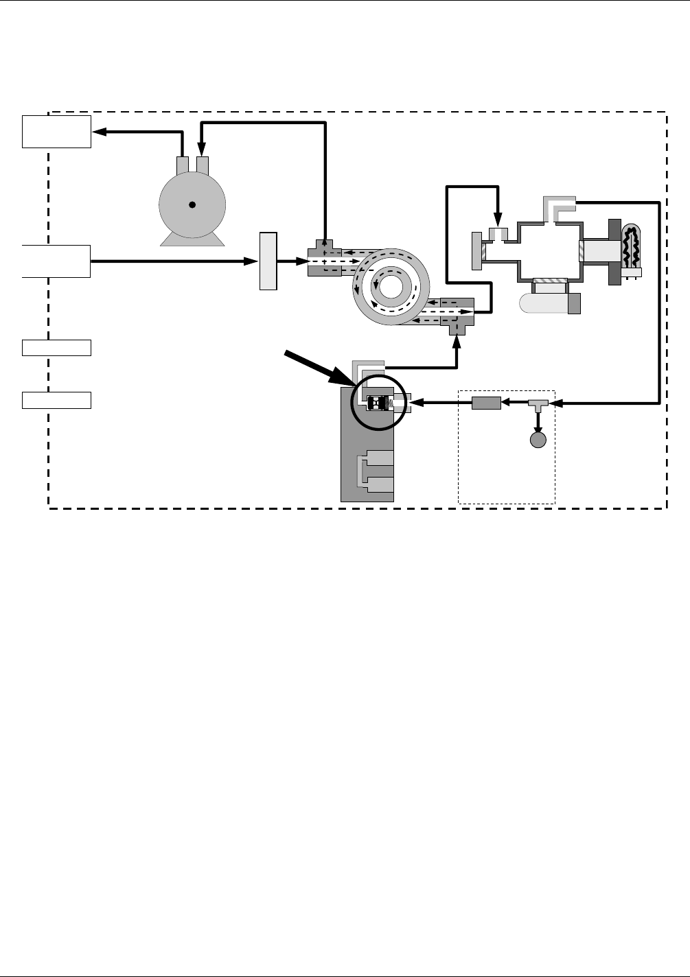
11.3.1. SAMPLE GAS FLOW
The Flow of gas through the M100E UV Fluorescence SO
2
Analyzer is created by a small internal pump that
pulls air though the instrument.
VACUUM MANIFOLD
FLOW
CONTROL
ASSY
EXHAUST TO OUTER
LAYER OF KICKER
SAMPLE GAS
INLET
SPAN GAS INLET
ZERO AIR INLET
SAMPLE FILTER
INSTRUMENT CHASSIS
EXHAUST GAS
OUTLET
KICKER EXHAUST
TO PUMP
HYDROCARBON
SCRUBBER
(KICKER)
UV
LAMP
PMT
SAMPLE
CHAMBER
FLOW
SENSOR
FLOW / PRESSURE
SENSOR PCA
SAMPLE
PRESSURE
SENSOR
PUMP
CRITICAL
FLOW
ORIFICE
Figure 11-7: Gas Flow and Location of Critical Flow Orifice
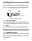
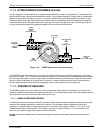
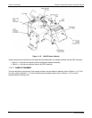
11.3.2. FLOW RATE CONTROL
The M100E uses a special flow control assembly located in the exhaust vacuum manifold (refer to Figure 11-7)
to maintain a constant flow rate of the sample gas through the instrument. This assembly consists of:
A critical flow orifice.
Two o-rings: Located just before and after the critical flow orifice, the o-rings seal the gap between the
walls of assembly housing and the critical flow orifice.
A spring: Applies mechanical force needed to form the seal between the o-rings, the critical flow orifice and
the assembly housing.
04515F DCN6048