Teledyne API M100E Analyzer Operation Manual Theory Of Operation
231
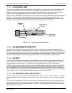
11.3.4. HYDROCARBON SCRUBBER (KICKER)
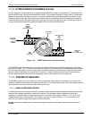
It is very important to ensure that the air supplied sample chamber is clear of hydrocarbons. To accomplish this
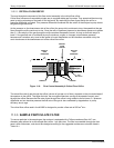
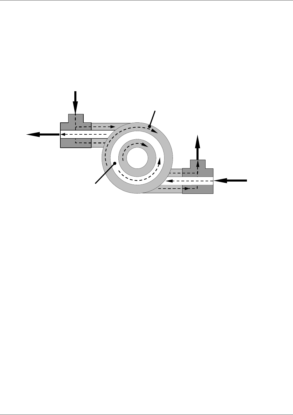
task the M100E uses a single tube permeation scrubber. The scrubber consists of a single tube of a specialized
plastic that absorbs hydrocarbons very well. This tube is located within outer flexible plastic tube shell. As gas
flows through the inner tube, hydrocarbons are absorbed into the membrane walls and transported through the
membrane wall and into the hydrocarbon free, purge gas flowing through the outer tube. This process is driven
by the hydrocarbon concentration gradient between the inner and outer of the tubes.
INNER
TUBE
(Ambient Air)
OUTER TUBE
(Clean Air)
SAMPLE AIR
FROM
PARTICULATE FILTER
CLEANED
SAMPLE AIR
TO
SAMPLE
CHAMBER
CLEAN
PURGE AIR
FROM
VACUUM MANIFOLD
USED PURGE AIR
TO
PUMP
AND
EXHAUST PORT
Figure 11-9: M100E Hydrocarbon Scrubber (Kicker)
In the M100E some of the cleaned air from the inner tube is returned to be used as the purge gas in the outer
tube (refer to Figure 11-9). This means that when the analyzer is first starte
d, the con
centration gradient between
the inner and outer tubes is not very large and the scrubber’s efficiency is relatively low. When the instrument is
turned on after having been off for more than 30 minutes, it takes a certain amount of time for the gradient to
become large enough for the scrubber to adequately remove hydrocarbons from the sample air.
11.3.5. PNEUMATIC SENSORS
The M100E uses two pneumatic sensors to verify gas streams. These sensors are located on a printed circuit
assembly, called the pneumatic pressure/flow sensor board. The flow simultaneously enters the sample pressure
sensor and the flow sensor from the outlet of the reaction cell.
11.3.5.1. SAMPLE PRESSURE SENSOR
An absolute pressure transducer plumbed to the input of the analyzer’s sample chamber is used to measure the
pressure of the sample gas before it enters the chamber. This upstream used to validate the critical flow
condition (2:1 pressure ratio) through the instrument’s critical flow orifice (refer to Section 11.3.2). Also, if the
Tempe
r
ature/Pressure Compensation (TPC) feature is turned on (refer to Section 11.7.3), the output of this
sens
or is also used to supply pressure data for that calculation.
The actual pressure measurement is viewable through the analyzer’s front panel display as the test function
PRESS.
04515F DCN6048


