Teledyne API M100E Analyzer Operation Manual Troubleshooting & Repair
261
12.2. STATUS LEDS
Several color-coded, light-emitting diodes (LEDs) are located inside the instrument to determine if the analyzer’s
CPU, I
2
C communications bus and relay board are functioning properly.
12.2.1. MOTHERBOARD STATUS INDICATOR (WATCHDOG)
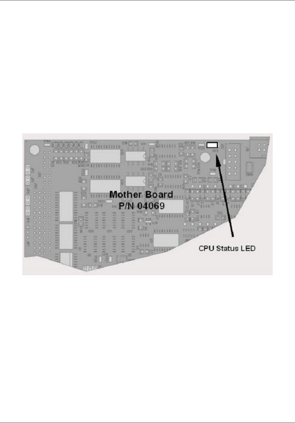
DS5, a red LED on the upper portion of the motherboard, just to the right of the CPU board, flashes when the
CPU is running the main program. After power-up, DS5 should flash on and off about once per second. If
characters are written to the front panel display but DS5 does not flash then the program files have become
corrupted. Contact Teledyne API’s Customer Service department.
If DS5 is not flashing 30 - 60 seconds after a restart and no characters have been written to the front panel
display, the firmware may be corrupted or the CPU may be defective. If DS5 is permanently off or permanently
on, the CPU board is likely locked up and should the analyzer not respond (either with locked-up or dark front
panel), then replace the CPU.
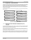
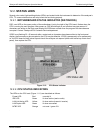
Figure 12-3: CPU Status Indicator
12.2.2. CPU STATUS INDICATORS
The LEDs on the CPU card (Figure 11-11) are described as follows:
Power LED Red normally lit
IDE LED Green lit when active (read or write)
LAN Link/Active LED Yellow lit when active (transmit / receive)
LAN Duplex LED Green lit when connected
MTBF LED Orange not used - ignore if lit
.
04515F DCN6048


