


Troubleshooting & Repair Teledyne API M100E Analyzer Operation Manual
278
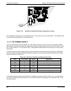
12.6.15. IZS OPTION
The zero/span valves and IZS options need to be enabled in the software (contact the factory on how to do this).
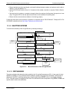
Refer to Figure 5-3 and Figure 5-4 for a flow diagram with zero/span valve or IZS option.
Che
ck for the physical presence of the valves or the IZS option.
Check that a working perm-tube is installed in the IZS oven assembly.
Check front panel for correct software configuration. When the instrument is in SAMPLE mode, the front
panel display should show CALS and CALZ buttons in the second line of the display. The presence of the
buttons indicates that the option has been enabled in software. In addition, the IZS option is enabled if the
TEST functions show a parameter named IZS TEMP.
The IZS option is heated with a proportional heater circuit and the temperature is maintained at 50° C ±1°. Check
the IZS TEMP function via front panel display (refer to Section 6.2.1) and the IZS
_
TEMP signal voltage using the
SIGNAL I/O function under the DIAG Menu (refer to Section 6.9.2).
At 50°
C, the temperature signal from the IZS thermistor should be around 2500 mV.
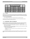
12.6.16. BOX TEMPERATURE
The box temperature sensor (thermistor) is mounted on the motherboard at the bottom, right corner of the CPU
board when looking at it from the front. It cannot be disconnected to check its resistance. Box temperature will
vary with, but will always read about 5° C higher than, ambient (room) temperature because of the internal
heating zones sample chamber and other devices.
To check the box temperature functionality, we recommend checking the BOX_TEMP signal voltage using the
SIGNAL I/O function under the DIAG Menu (refer to Section 6.9.2).
At about 30°
C (5 above typical room temperature), the signal should be around 1500 mV. We
recommend using a certified or calibrated external thermometer / temperature sensor to verify the
accuracy of the box temperature.
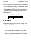
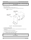
12.6.17. PMT TEMPERATURE
PMT temperature should be low and constant. It is more important that this temperature is maintained constant
than it is to maintain it low. The PMT cooler uses a Peltier, thermo-electric element powered by 12 VDC from the
switching power supply PS2. The temperature is controlled by a proportional temperature controller located on
the preamplifier board. Voltages applied to the cooler element vary from +/- 0.1 to +/- 12 VDC. The temperature
set point (hard-wired into the preamplifier board) will vary by about ±1 C due to component tolerances. The
actual temperature will be maintained to within 0.1 C around that set point.
On power-up of the analyzer, the front panel enables the user to watch that temperature drop from about
ambient temperature down to its set point of 6-8° C.
If the temperature fails to drop after 20 minutes, there is a problem in the cooler circuit.
If the control circuit on the preamplifier board is faulty, a temperature of -1 C is reported.
04515F DCN6048