Teledyne API M100E Analyzer Operation Manual Remote Operation and Advanced Features
133
7.1.8. MULTIDROP RS-232 SET UP
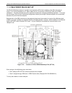
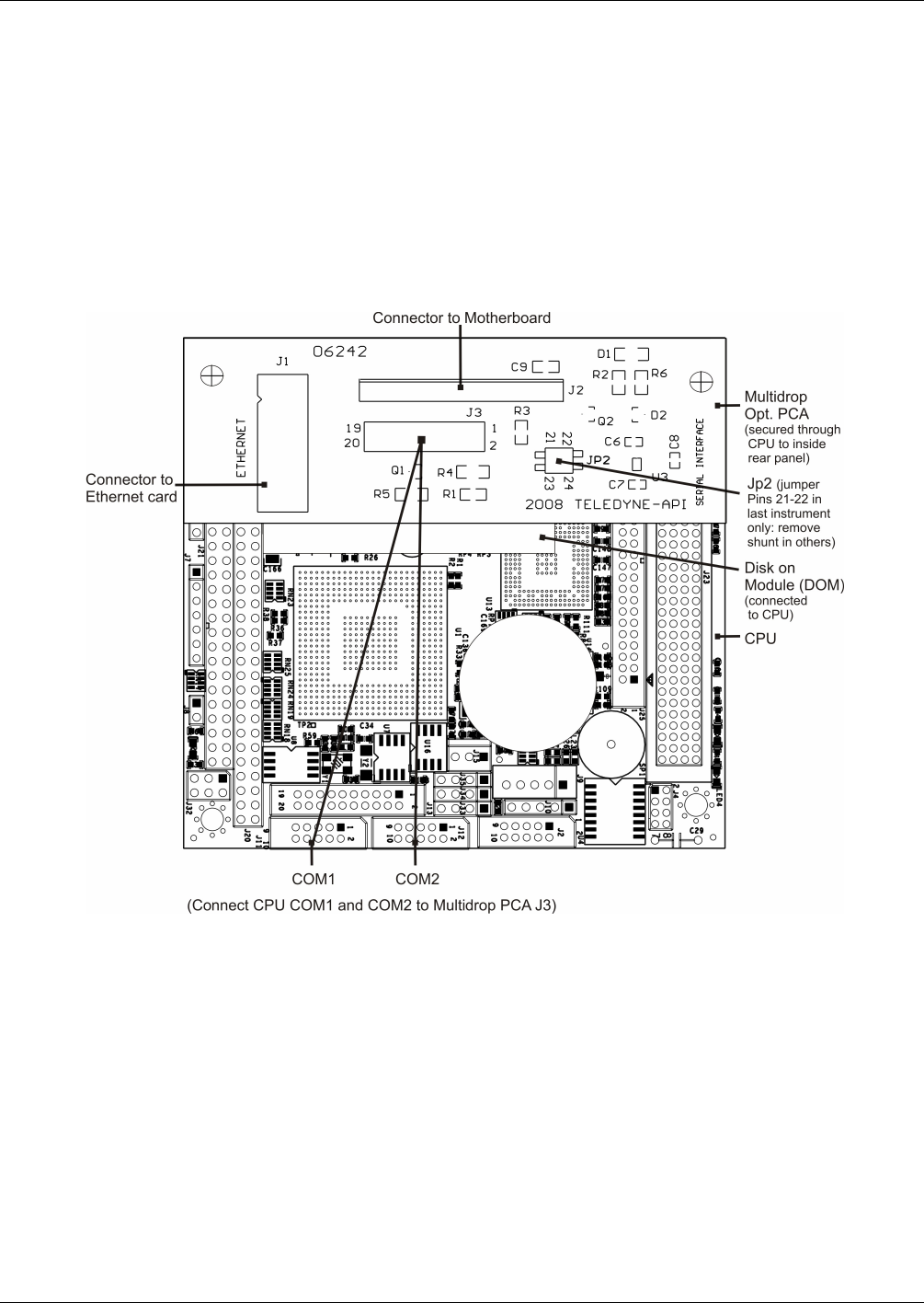
The RS-232 Multidrop consists of a printed circuit assembly (PCA) that is seated on the CPU card (refer to
Figure 7-12), and is connected by a Y-ribbon cable from its J3 con
nector to the CPU’s COM1 and COM2
connectors.. This PCA includes all circuitry required to enable your analyzer for Multidrop operation. It converts
the instrument’s RS-232 port to Multidrop configuration allowing up to eight E Series analyzers to be connected
the same I/O port of the host computer.
Because both of the DB9 connectors on the analyzer’s back panel are needed to construct the Multidrop chain,
COM2 is no longer available for separate RS-232 or RS-485 operation, however, with the addition of an Ethernet
Option (OPT 63A, refer to Sections 5.8.4 and 7.1.6) the COM2 port is available for communication over a
10BaseT LA
N.
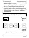
Figure 7-12: Location of JP2 on RS232-Multidrop PCA (OPT 62)
Each analyzer in the Multidrop chain must have:
One Teledyne API’s OPT 62 (internal multidrop card) installed
One 6’ straight-through, DB9 male DB9 Female cable (Teledyne API P/N WR0000101)
To set up the network, for each analyzer:
04515F DCN6048


