Remote Operation and Advanced Features Teledyne API M100E Analyzer Operation Manual
124
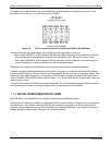
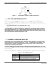
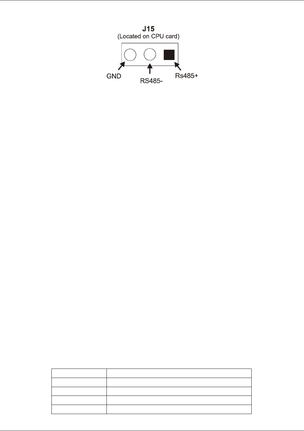
Figure 7-7: CPU Connector Pin-Outs for COM2 in RS-485 Mode
7.1.5. DTE AND DCE COMMUNICATION
RS-232 was developed for allowing communications between data terminal equipment (DTE) and data
communication equipment (DCE). Basic terminals always fall into the DTE category whereas modems are
always considered DCE devices. The difference between the two is the pin assignment of the Data Receive and
Data Transmit functions.
DTE devices receive data on pin 2 and transmit data on pin 3.
DCE devices receive data on pin 3 and transmit data on pin 2.
To allow the analyzer to be used with terminals (DTE), modems (DCE) and computers (which can be either), a
switch mounted below the serial ports on the rear panel allows the user to set the configuration of RS-232 for
one of these two modes. This switch exchanges the Receive and Transmit lines on RS-232 emulating a cross-
over or null-modem cable. The switch has no effect on COM2.
7.1.6. ETHERNET CARD CONFIGURATION
When equipped with the optional Ethernet interface, the analyzer can be connected to any standard 10BaseT
Ethernet network via low-cost network hubs, switches or routers. The interface operates as a standard TCP/IP
device on port 3000. This allows a remote computer to connect through the internet to the analyzer using
APICOM, terminal emulators or other programs.
The firmware on board the Ethernet card automatically sets the communication modes and baud rate (115,200
Baud) for the COM2 port. Once the Ethernet option is installed and activated, the COM2 submenu is replaced
by a new submenu, INET. This submenu is used to manage and configure the Ethernet interface with your LAN
or Internet Server(s).
The card has four LEDs that are visible on the rear panel of the analyzer, indicating its current operating status.
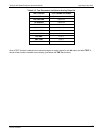
Table 7-1: Ethernet Status Indicators
LED FUNCTION
LNK (green) ON when connection to the LAN is valid.
ACT (yellow) Flickers on any activity on the LAN.
TxD (green) Flickers when the RS-232 port is transmitting data.
RxD (yellow) Flickers when the RS-232 port is receiving data.
04515F DCN6048


