


Theory Of Operation Teledyne API M100E Analyzer Operation Manual
230
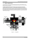
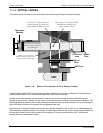
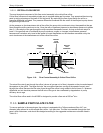
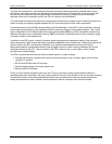
11.3.2.1. CRITICAL FLOW ORIFICE
The most important component of this flow control assembly is the critical flow orifice.
Critical flow orifices are a remarkably simple way to regulate stable gas flow rates. They operate without moving
parts by taking advantage of the laws of fluid dynamics. By restricting the flow of gas though the orifice, a
pressure differential is created. This pressure differential combined with the action of the analyzer’s pump draws
the gas through the orifice.
As the pressure on the downstream side of the orifice (the pump side) continues to drop, the speed that the gas
flows though the orifice continues to rise. Once the ratio of upstream pressure to downstream pressure is greater
than 2:1, the velocity of the gas through the orifice reaches the speed of sound. As long as that ratio stays at
least 2:1 the gas flow rate is unaffected by any fluctuations, surges, or changes in downstream pressure
because such variations only travel at the speed of sound themselves and are therefore cancelled out by the
sonic shockwave at the downstream exit of the critical flow orifice.
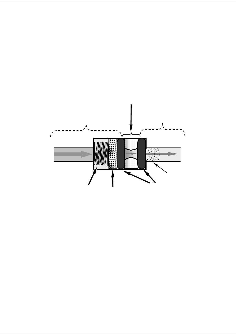
SPRING
O-RINGS
FILTER
CRITICAL
FLOW
ORIFICE
A
REA OF
LOW
PRESSURE
AREA OF
HIGH
PRESSURE
Sonic
Shockwave
Figure 11-8: Flow Control Assembly & Critical Flow Orifice
The actual flow rate of gas through the orifice (volume of gas per unit of time), depends on the size and shape of
the aperture in the orifice. The larger the hole, the more gas molecules, moving at the speed of sound, pass
through the orifice. Because the flow rate of gas through the orifice is only related to the minimum 2:1 pressure
differential and not absolute pressure the flow rate of the gas is also unaffected by degradations in pump
efficiency due to age.
The critical flow orifice used in the M100E is designed to provide a flow rate of 650 cm
3
/min.
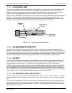
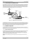
11.3.3. SAMPLE PARTICULATE FILTER
To remove particles in the sample gas, the analyzer is equipped with a Teflon membrane filter of 47 mm
diameter (also referred to as the sample filter) with a 1 µm pore size. The filter is accessible through the front
panel, which folds down, and should be changed according to the suggested maintenance schedule listed in
Table 10-1.
04515F DCN6048